How to replace the lower control arms 2009-2014 Ford F-150
To replace the lower control arms on your F-150 we’re here to help. You will be asked to lift the vehicle, remove the control arm, rescrew the screws on the engine subframe side and other steps you’ll need to follow in the correct order. You can follow this tutorial of 19 chapters in 120 minutes. Take your ratchet and your wheel lug wrench and let’s get started!
Duration
120 minutes
Number of steps
19
Difficulty out of 5
3
Average savings
$90
Parts You Will Need
Tools You Will Need
Step-by-Step Installation
Chapter 1:
Set up
Step 1/1
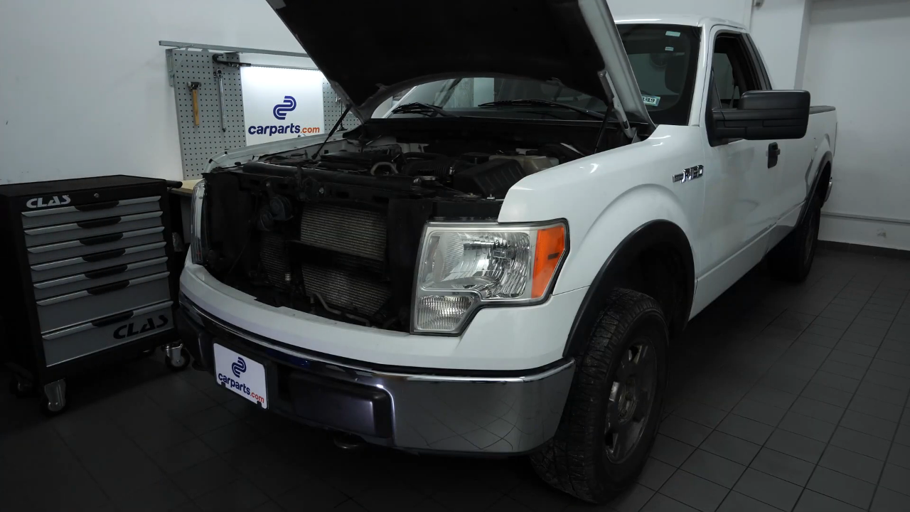
Turn your engine off, set the parking brake, pull on the bonnet release handle, open the bonnet.
Chapter 2:
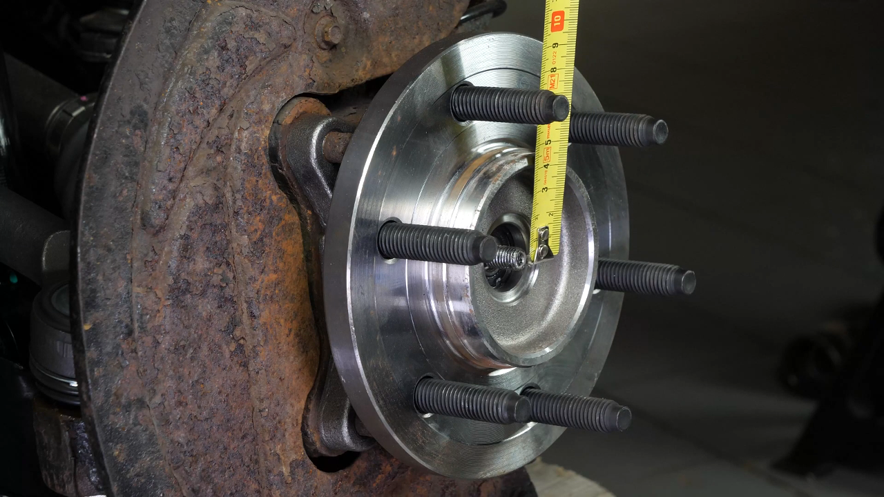
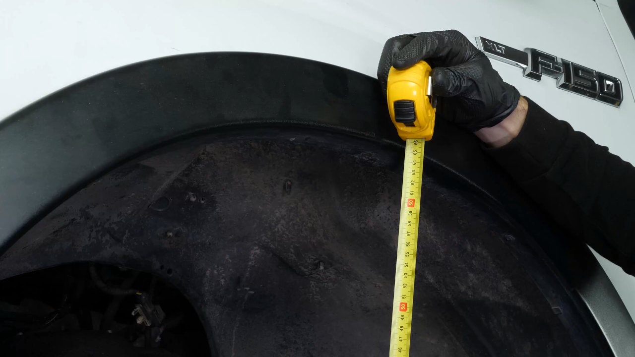
Measure
Step 1/1
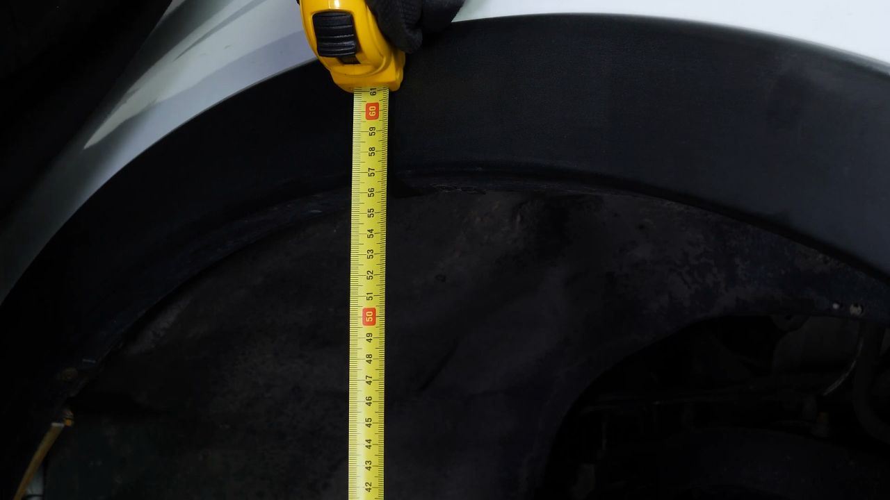
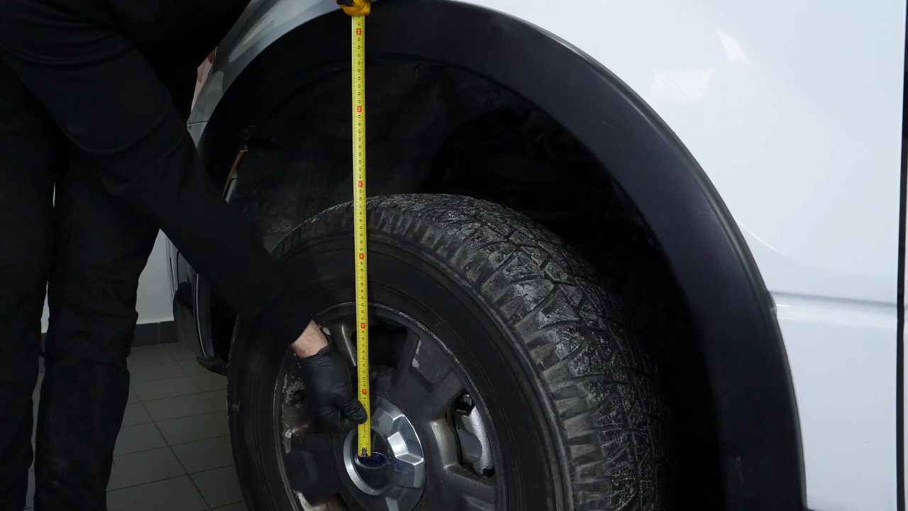
Before lifting your vehicle, it is necessary to measure the distance between the centre of your wheel and the wheel arch. This will allow you to achieve an optimal tightening of the silentblock equipped elements in their initial position.
Chapter 3:
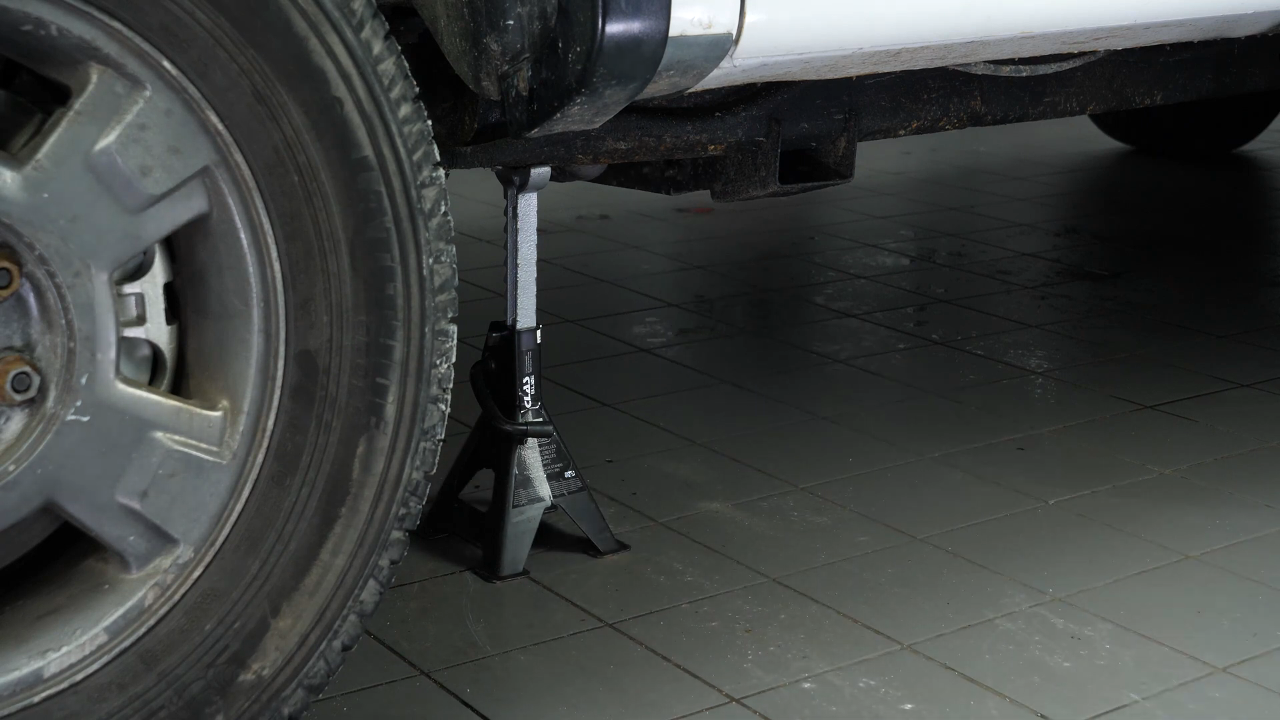
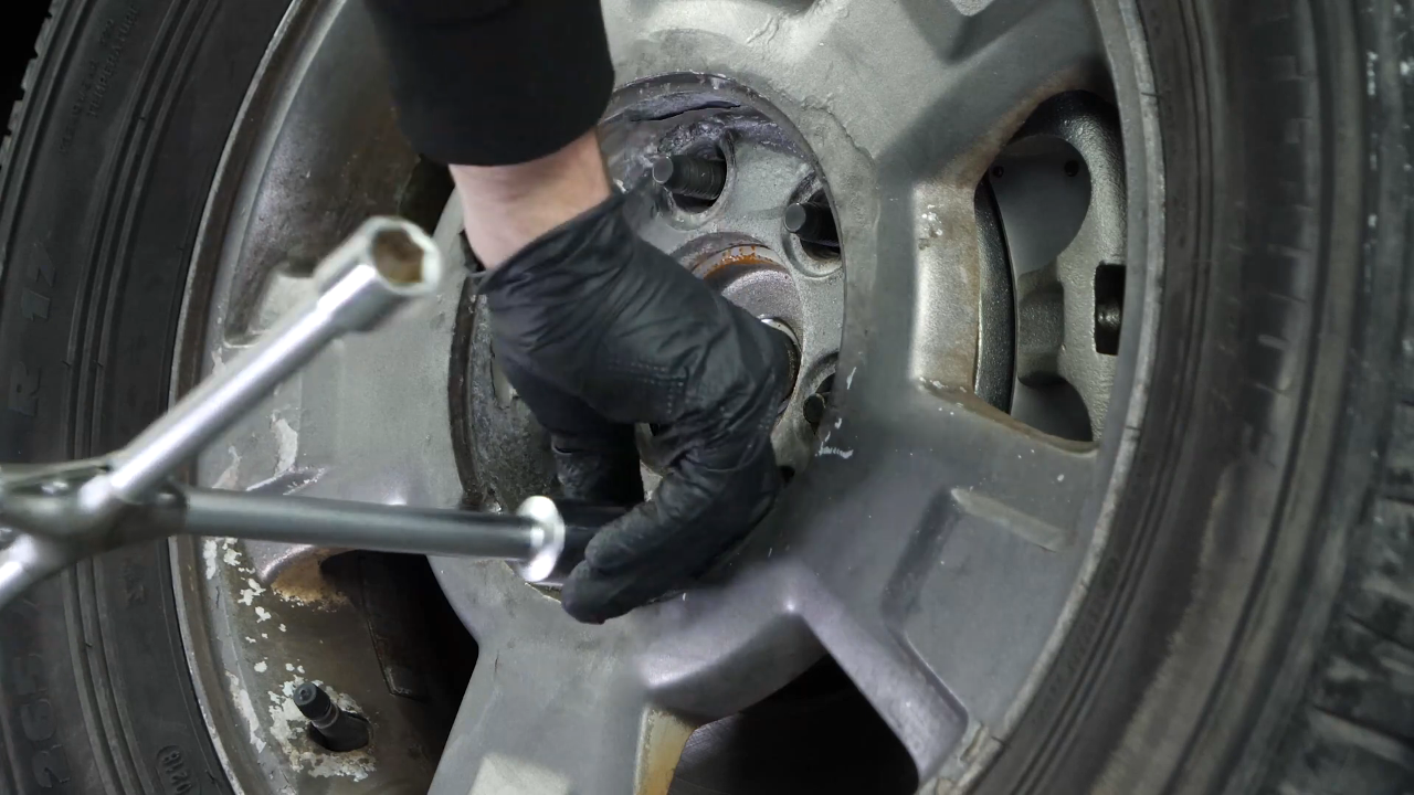
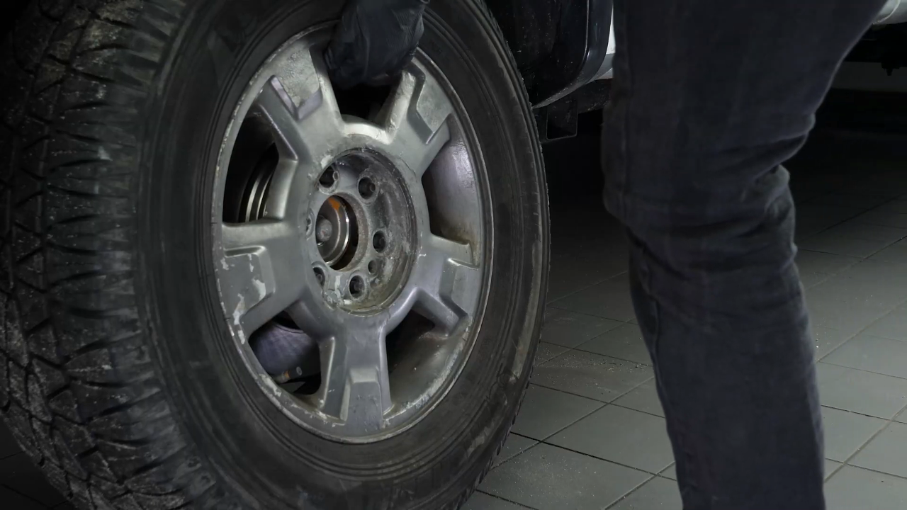
Lift the vehicle
Step 1/1
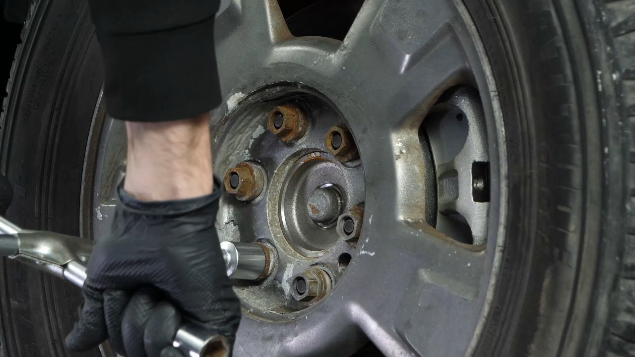
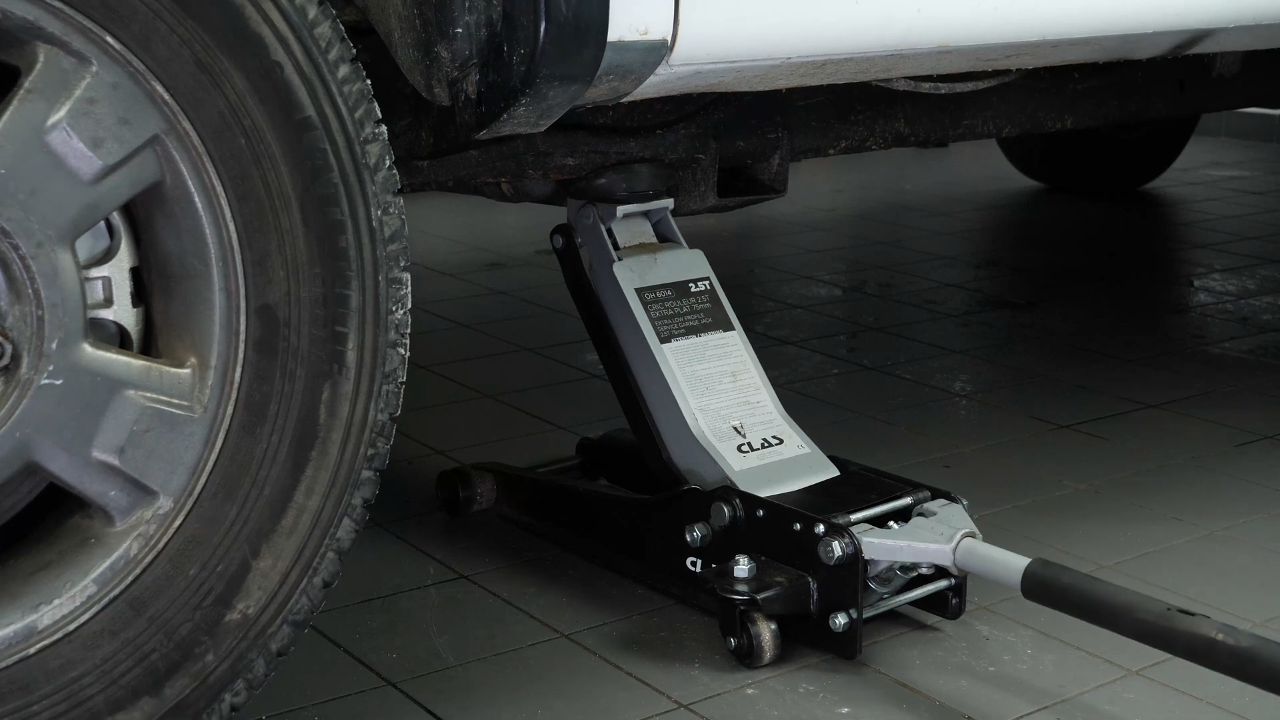
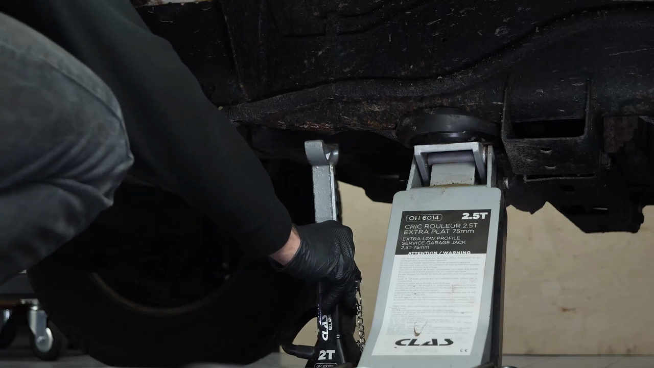
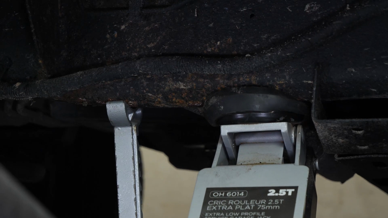
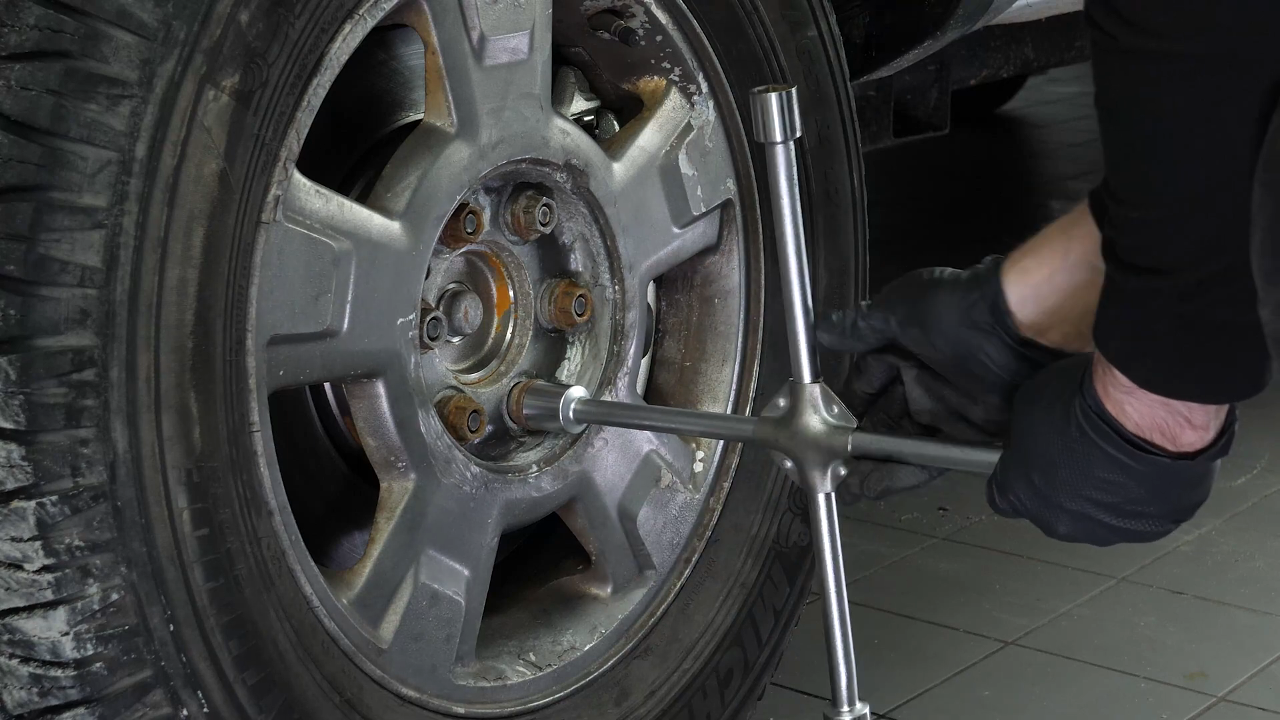
Loosen the stud bolts on the front wheels. Lift the front of your vehicle. Place the vehicle on the axle stands. To be able to replace the lower control arms on your vehicle, you need to remove the wheels to gain complete access to the suspension system. Don’t forget to put the wheels under the vehicle!
Chapter 4:
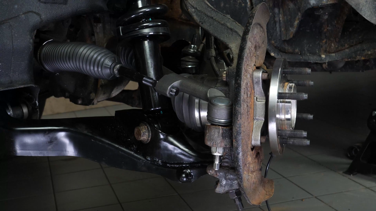
Remove various components
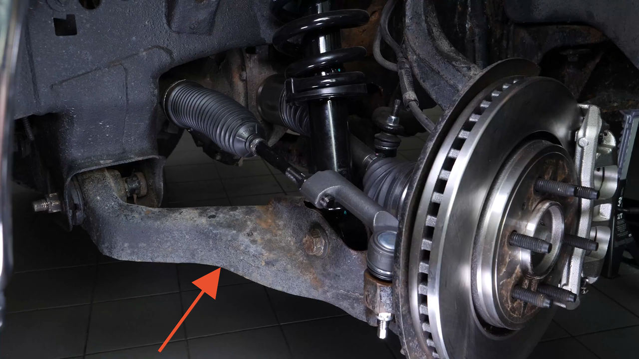
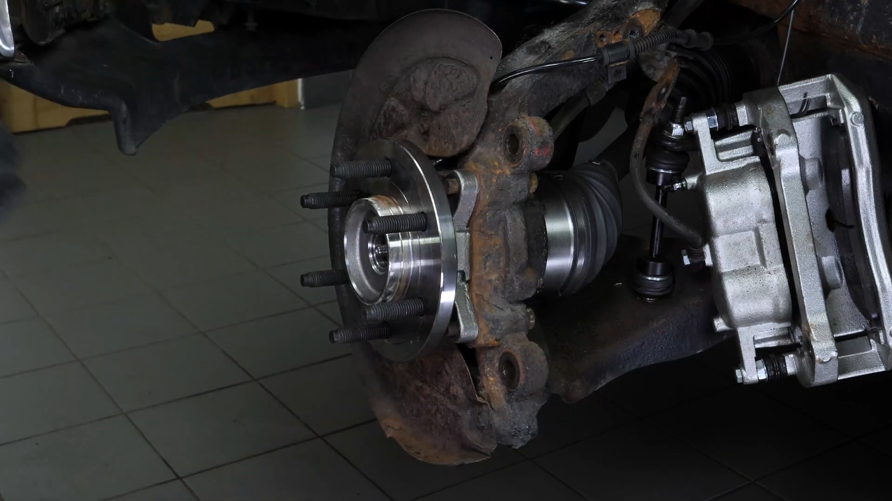
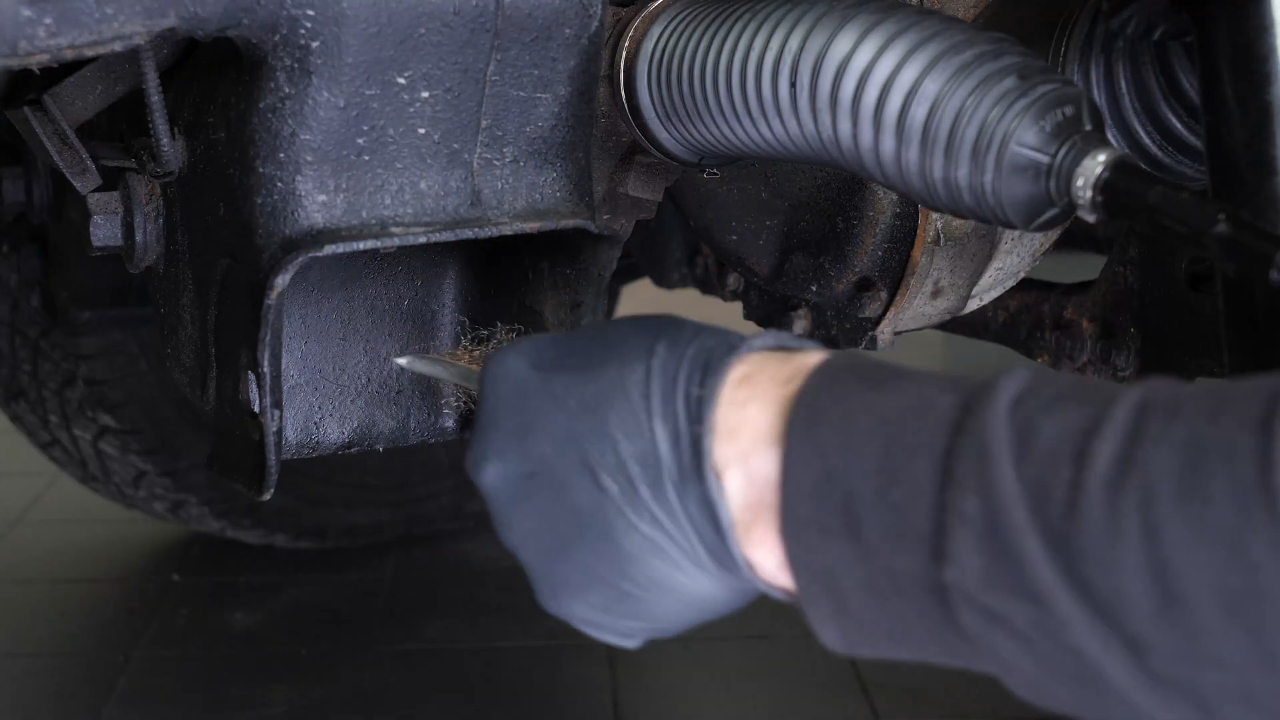
Step 1/3
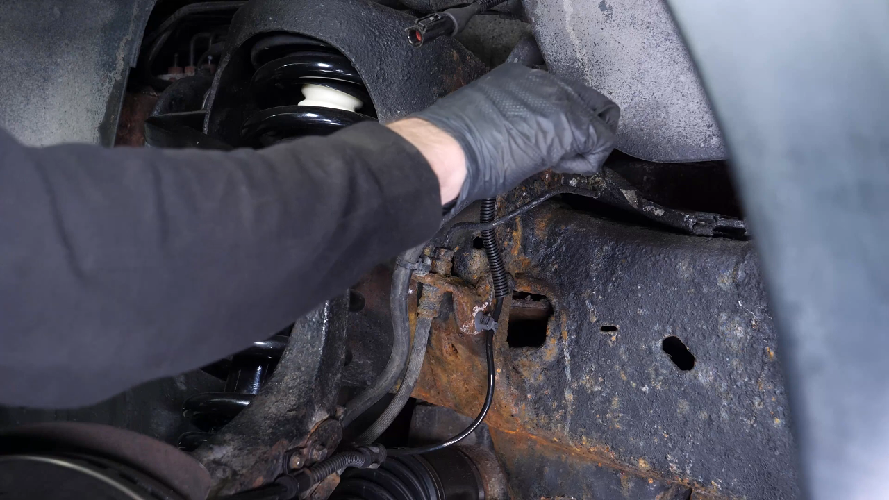
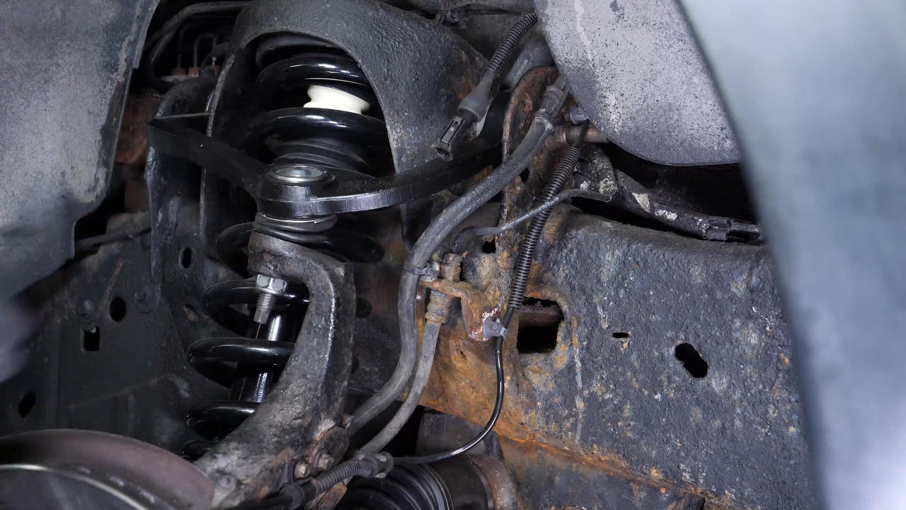
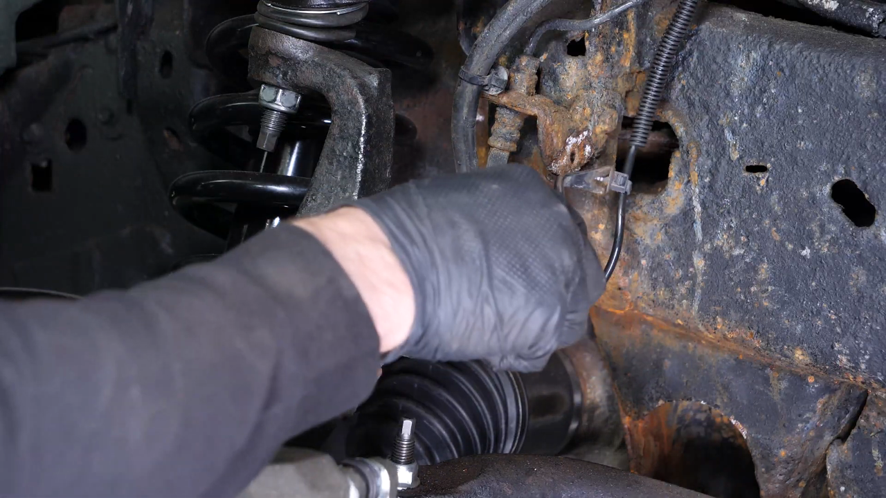
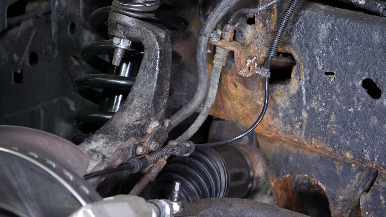
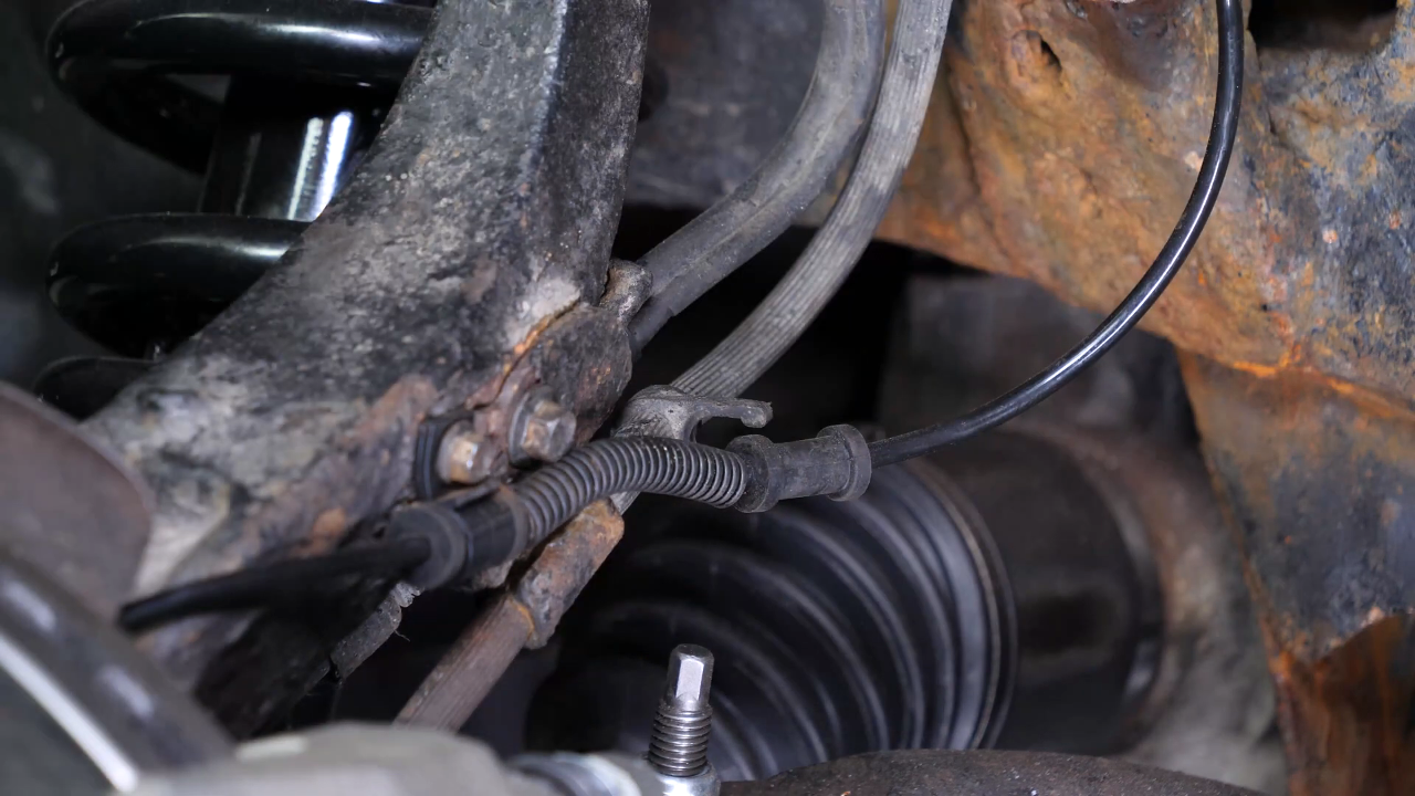
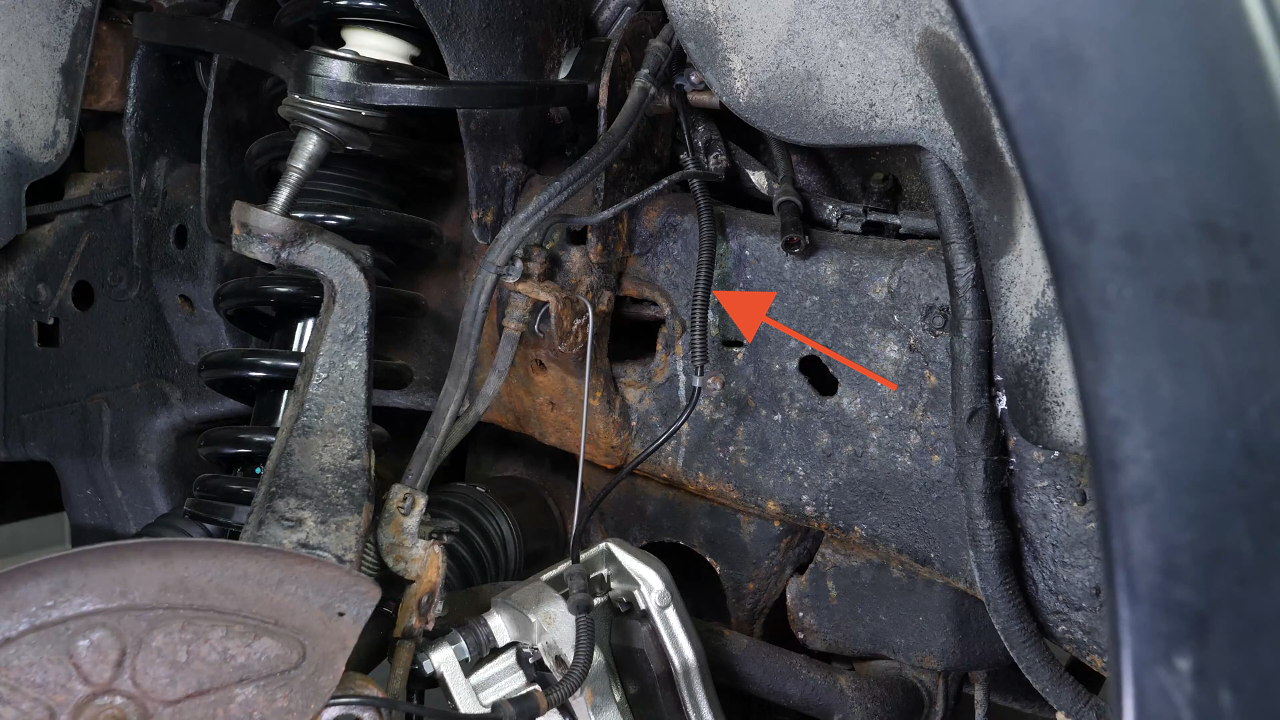
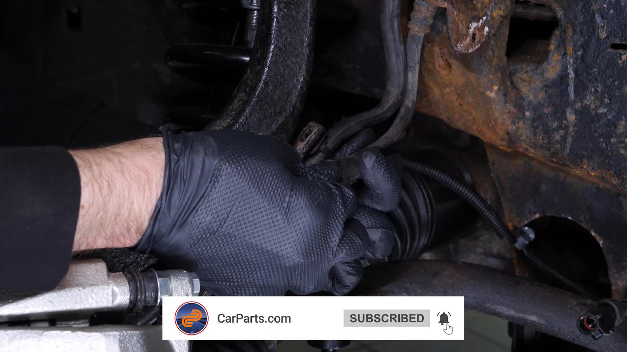
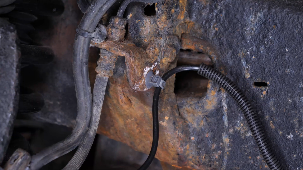
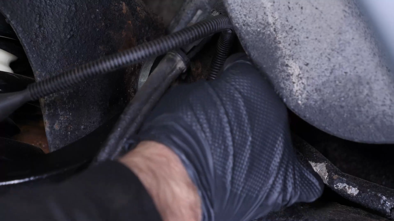
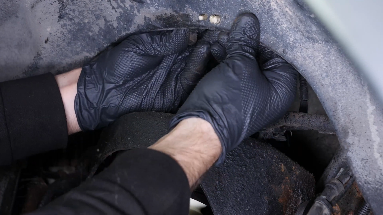
You can now see your car’s lower control arm. Start by unclipping the ABS sensor cable connection from the mudguard.
Chapter 4:
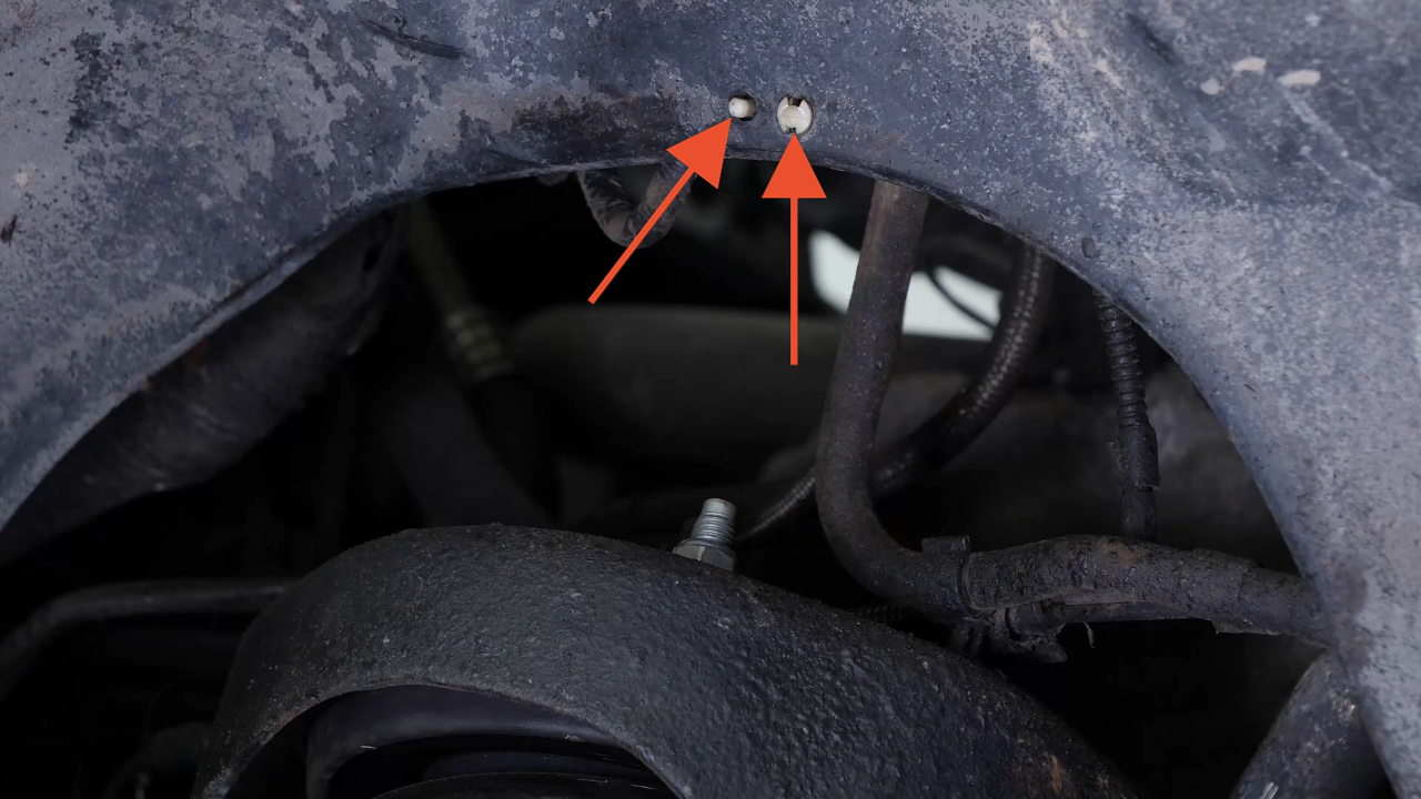
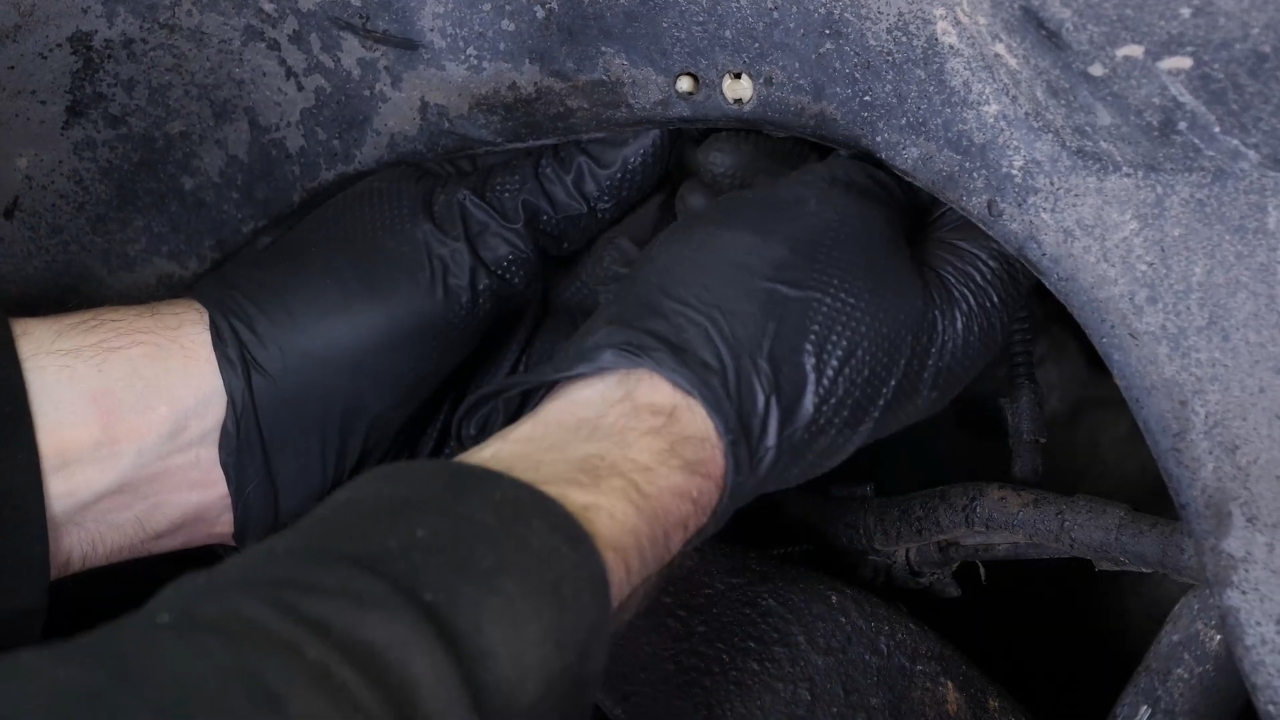
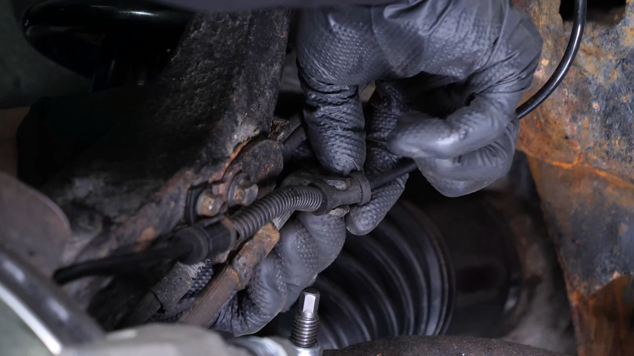
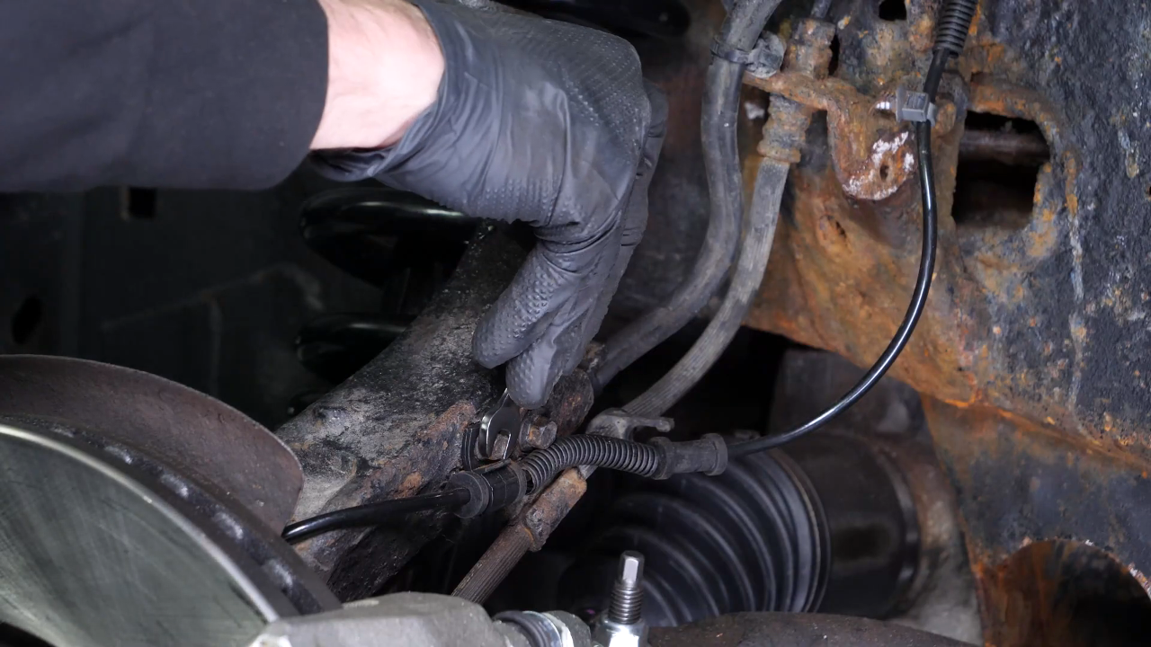
Step 2/3
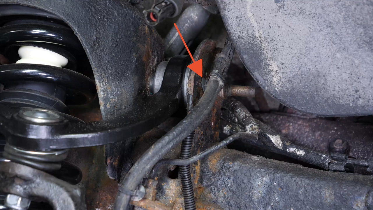
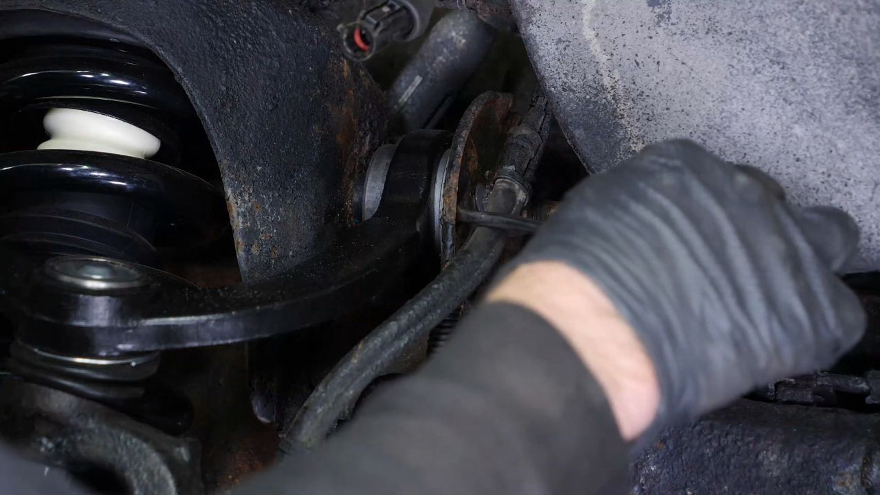
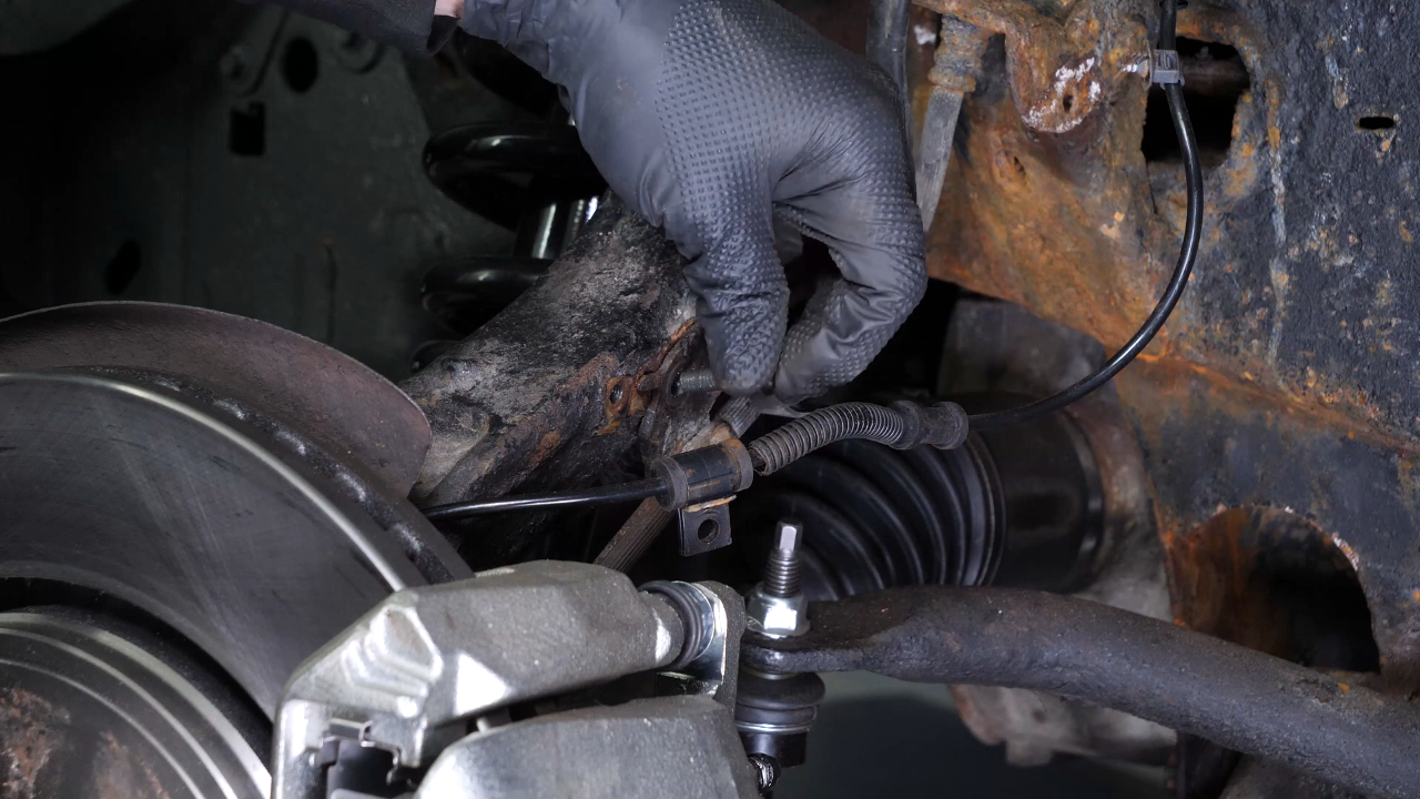
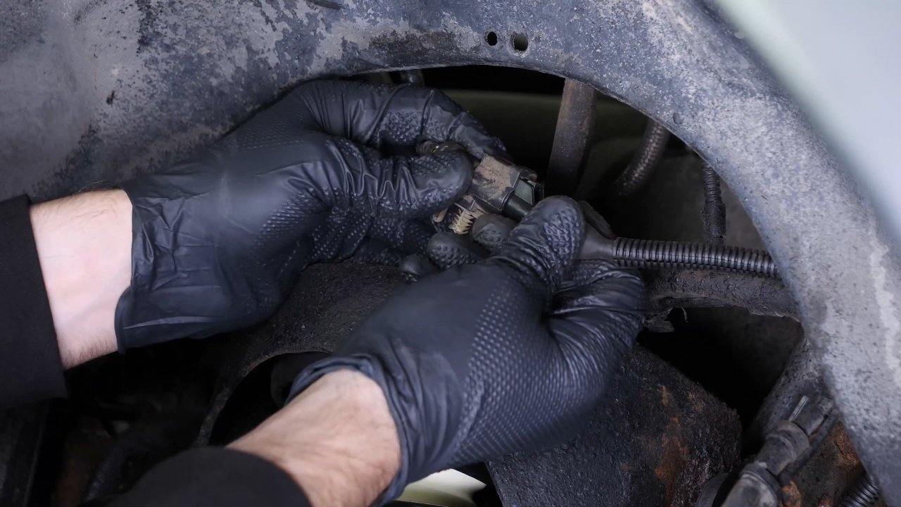
Unclip the two cable attachment points using a fork. Then disconnect it from the brake hose.
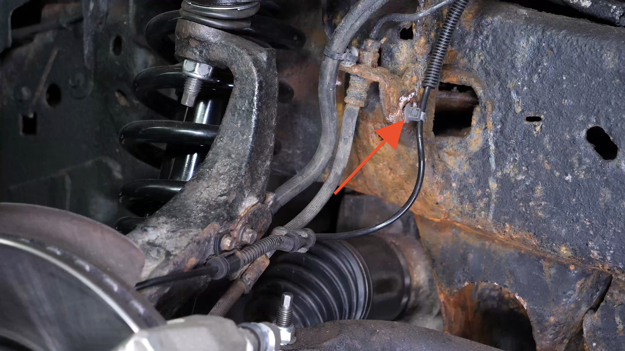
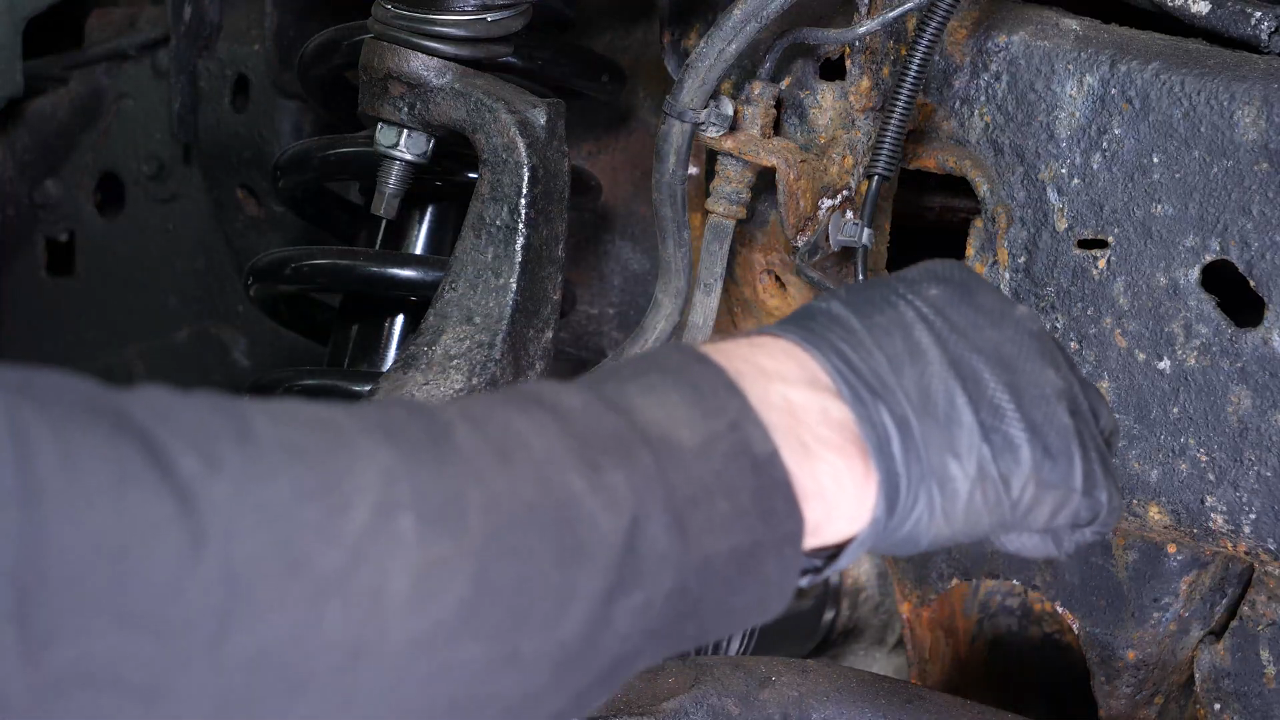
Chapter 4:
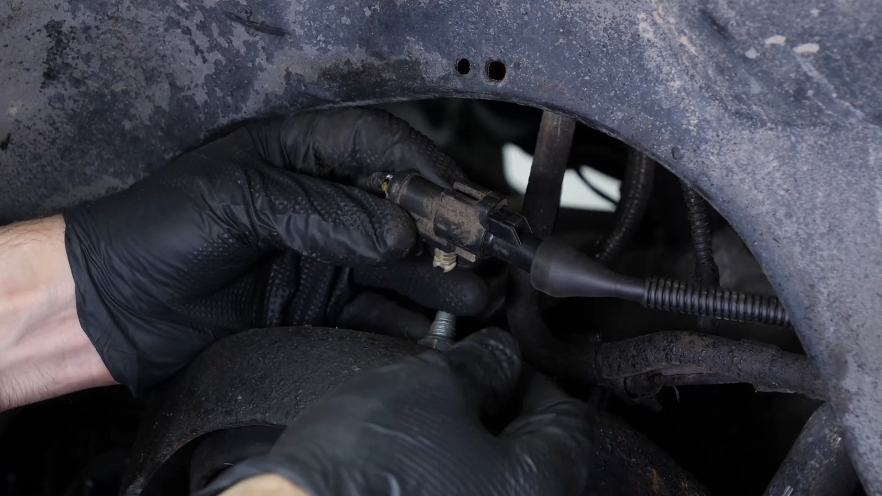
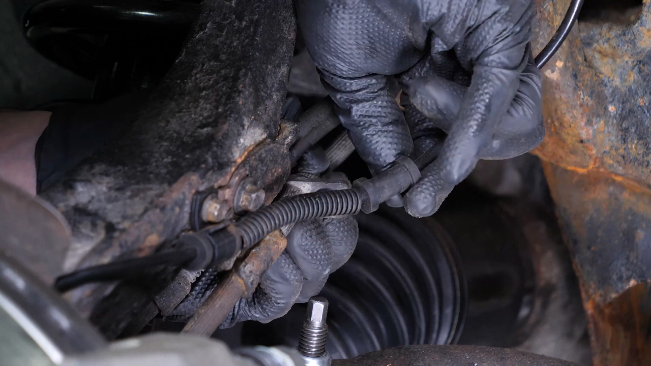
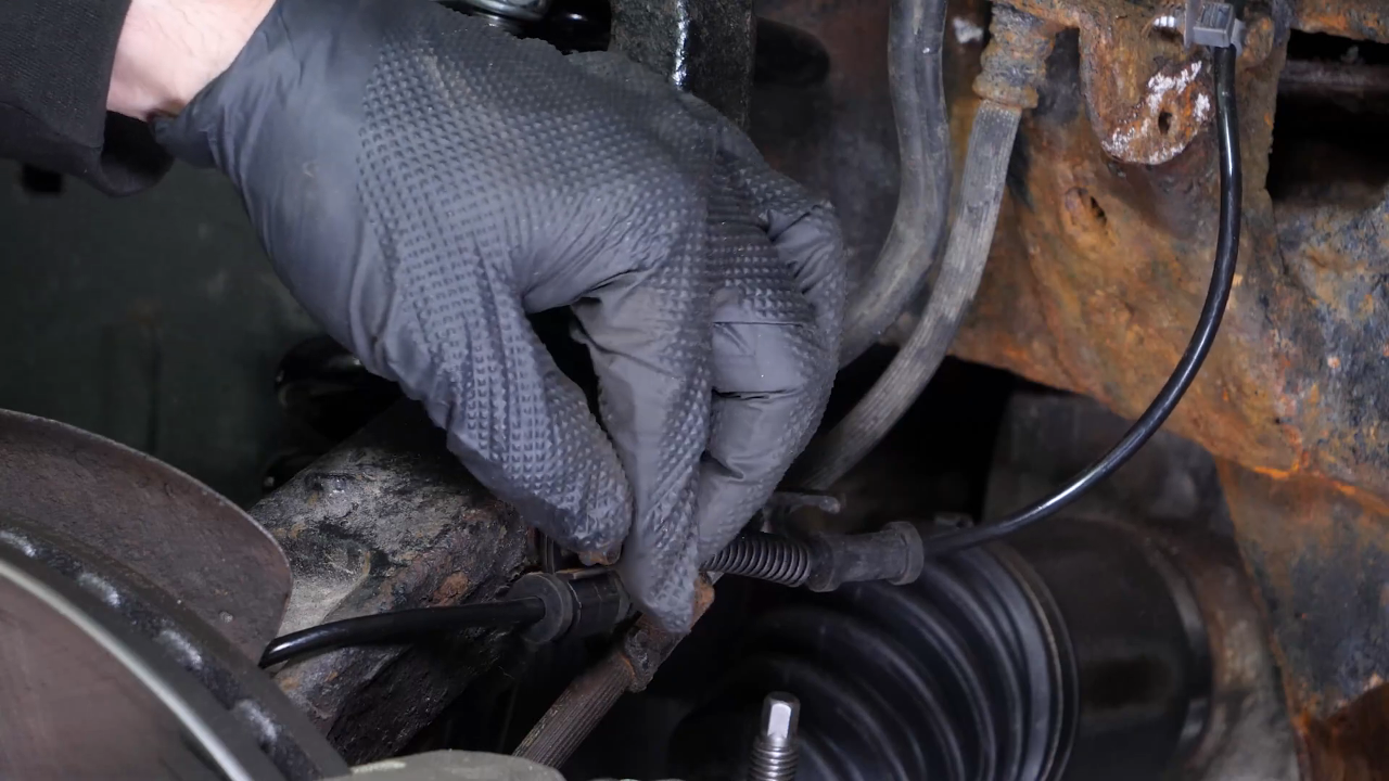
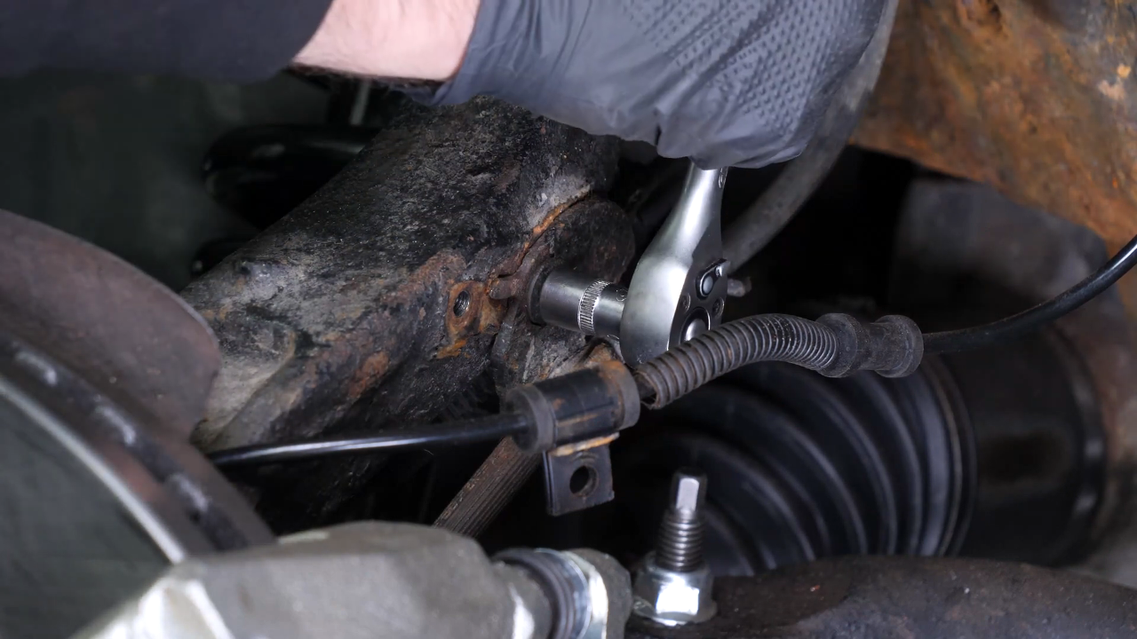
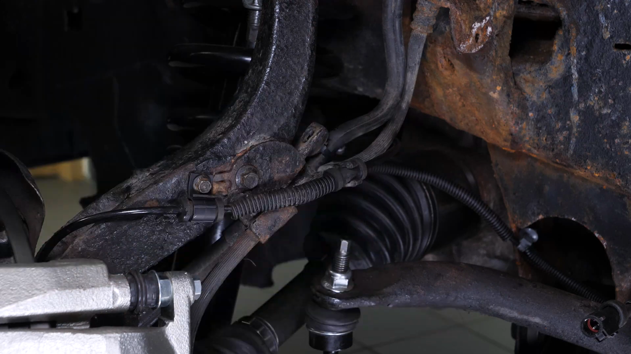
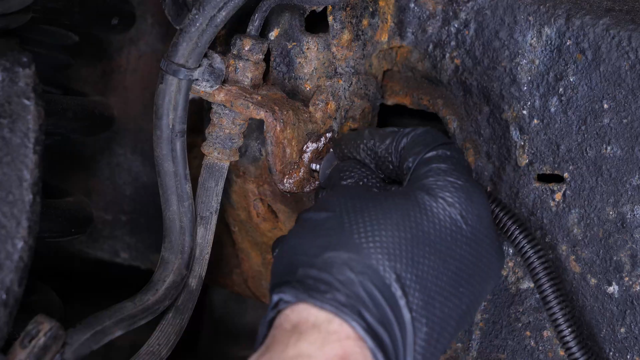
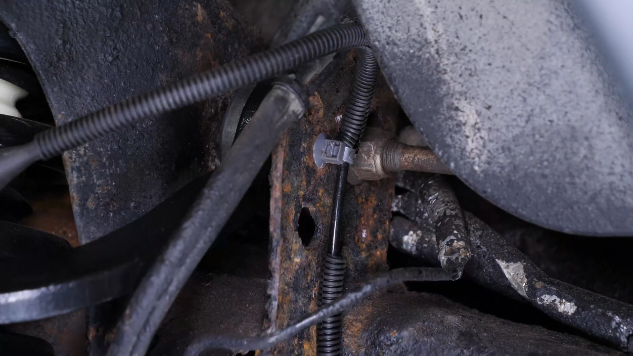
Step 3/3
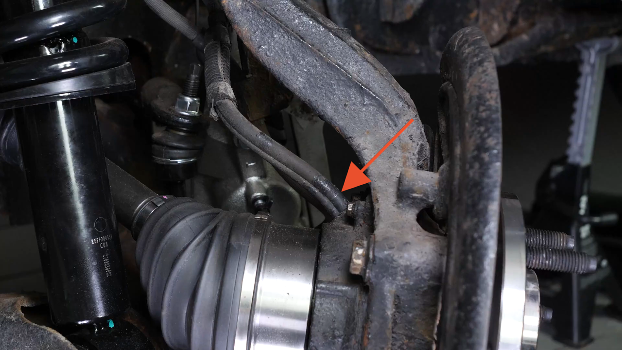
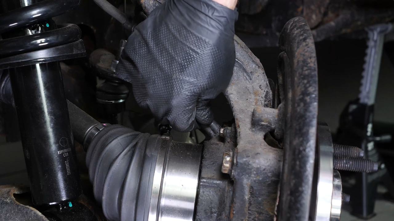
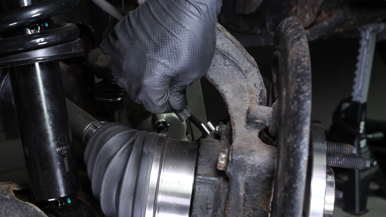
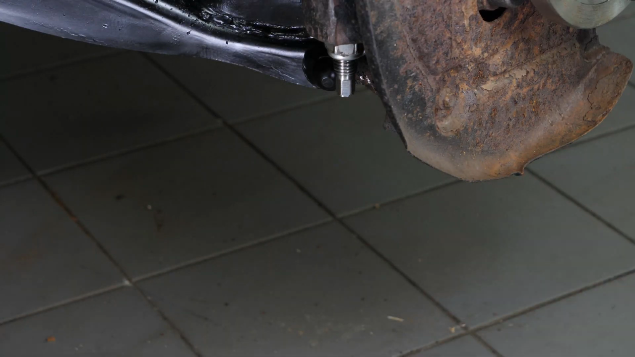
Finally, using an 8mm spanner, unscrew the screw that holds it to the wheel knuckle. Using a ratchet and a 10mm socket, unscrew the brake hose clamp from the wheel knuckle.
Chapter 5:
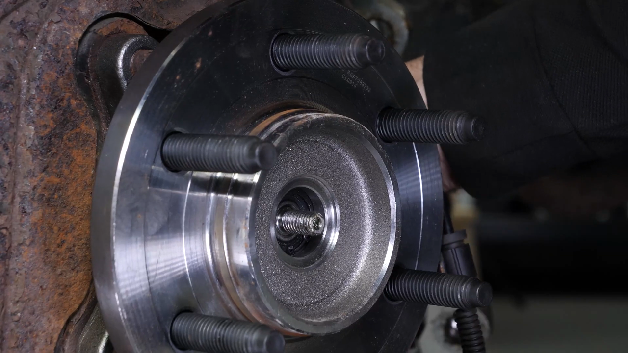
Unscrew the CV axle nut
Step 1/1
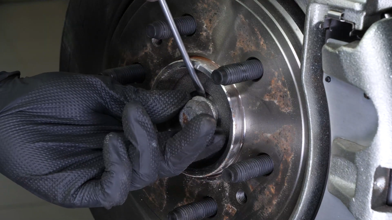
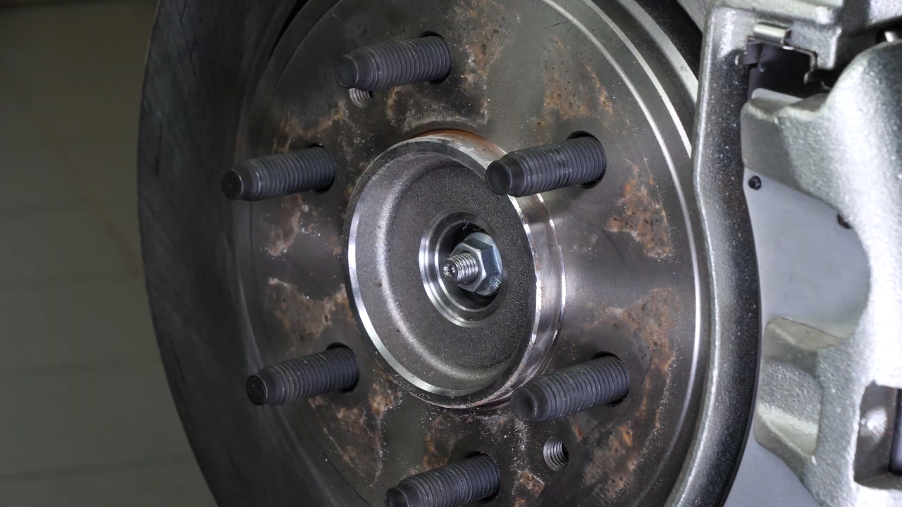
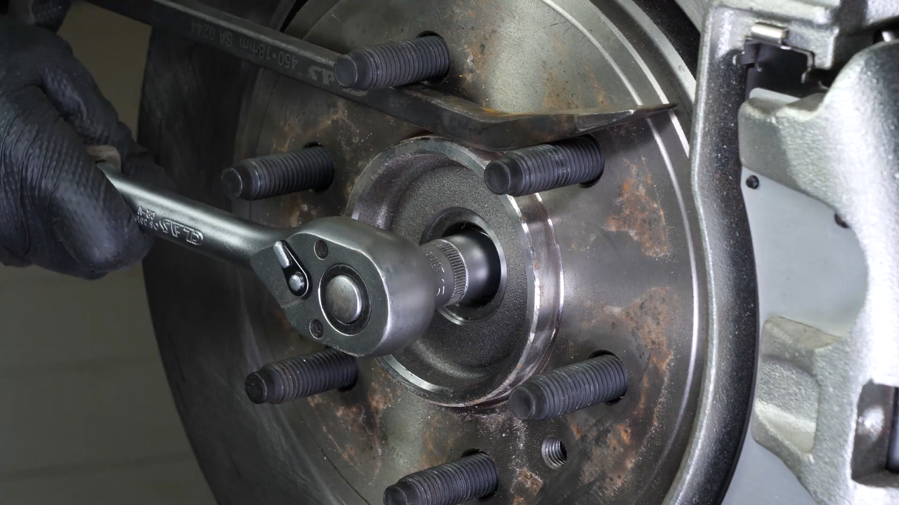
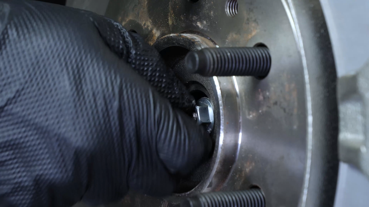
Using a flathead screwdriver, remove the nut cover from the hub. Then, locking the hub rotation with a crowbar, unscrew the hub nut using a ratchet and a 15mm socket.
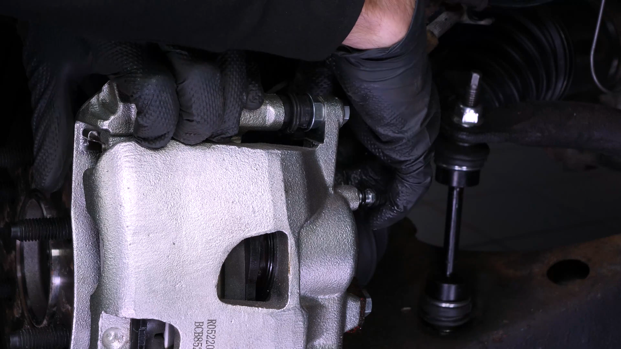
Chapter 6:
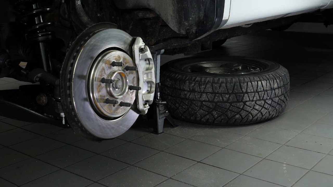
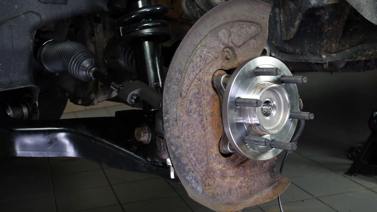
Remove the brake system
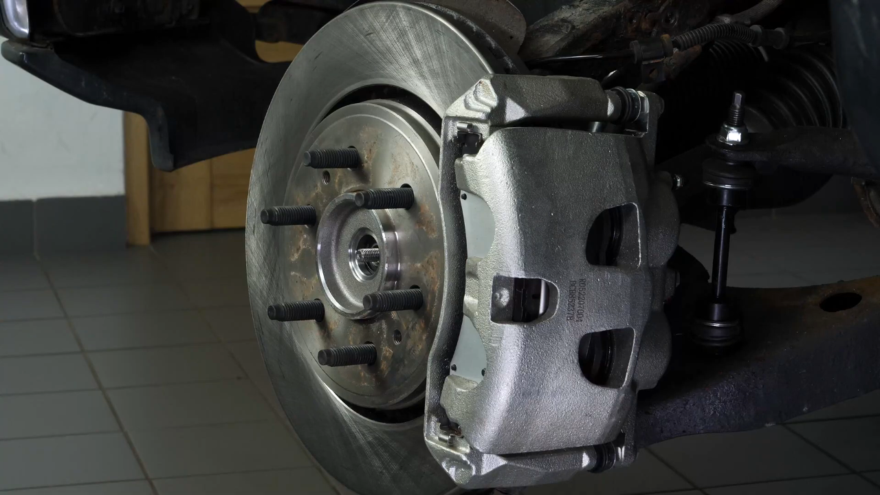
Step 1/2
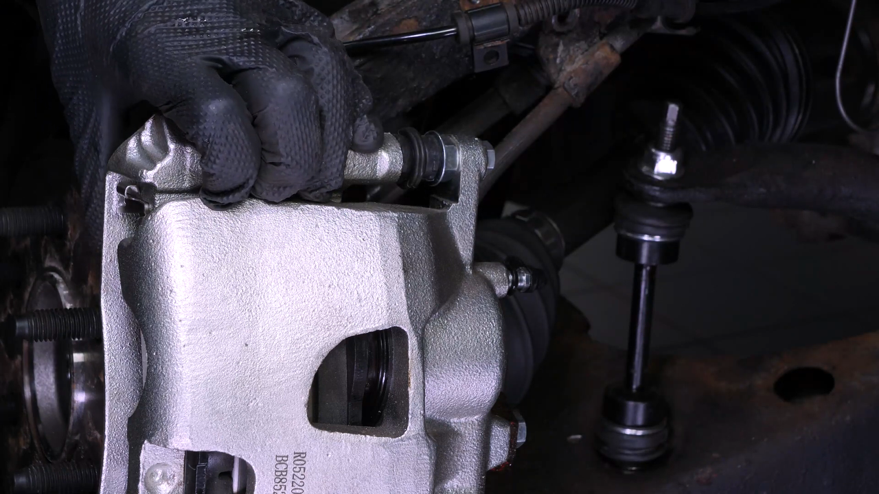
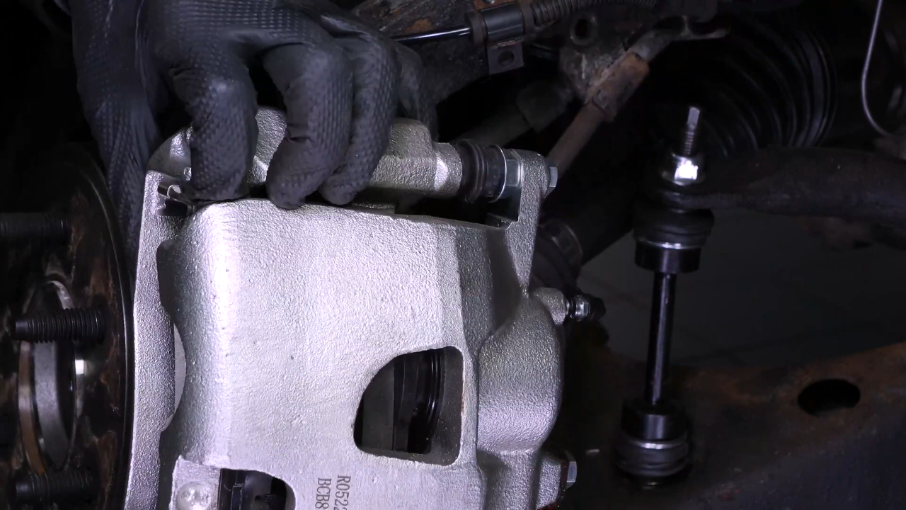
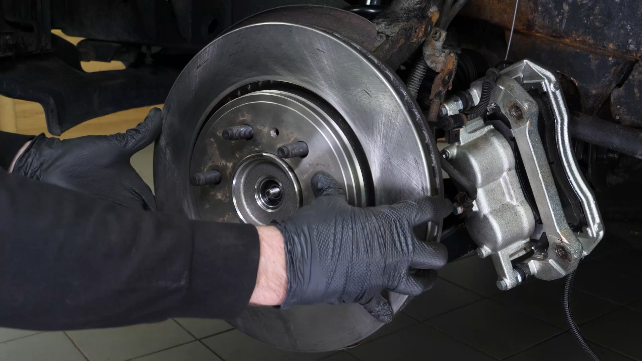
Turn the disk inward to make this operation easier. It is now necessary to remove the caliper assembly.
Chapter 6:
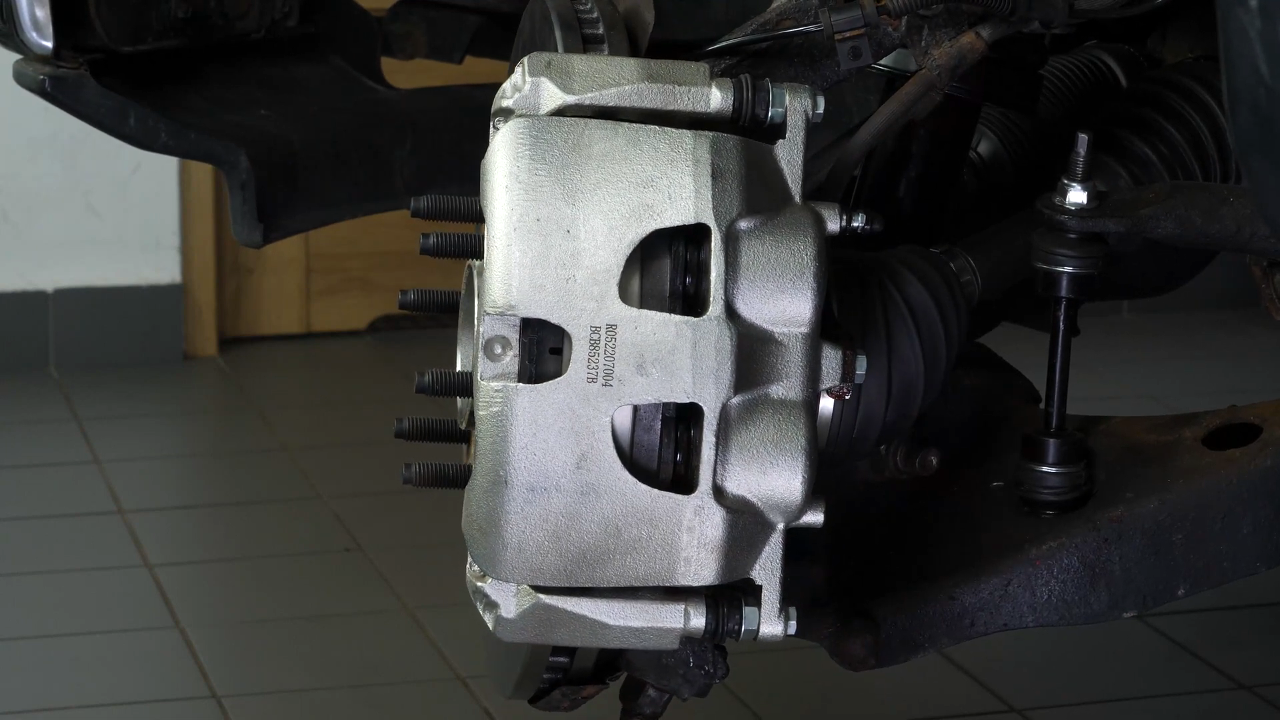
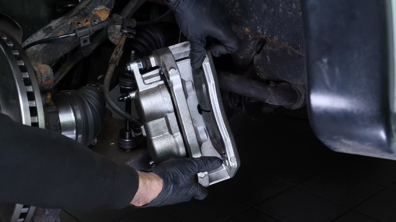
Step 2/2
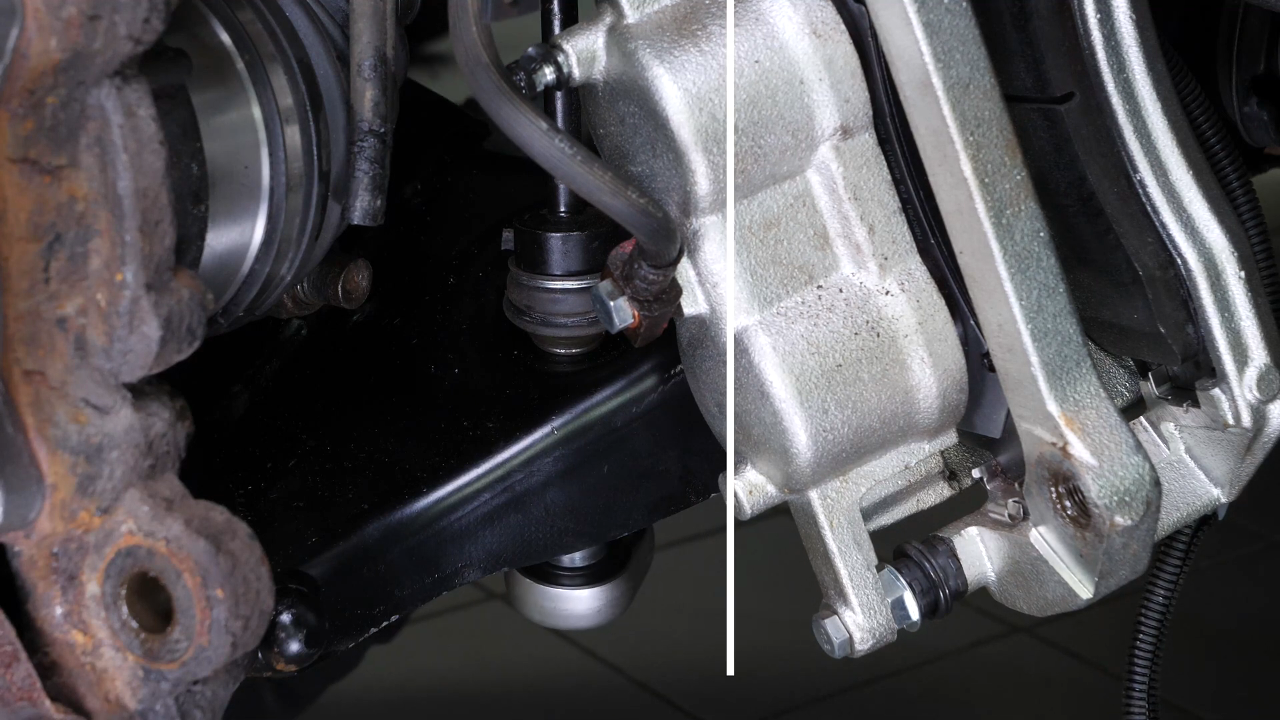
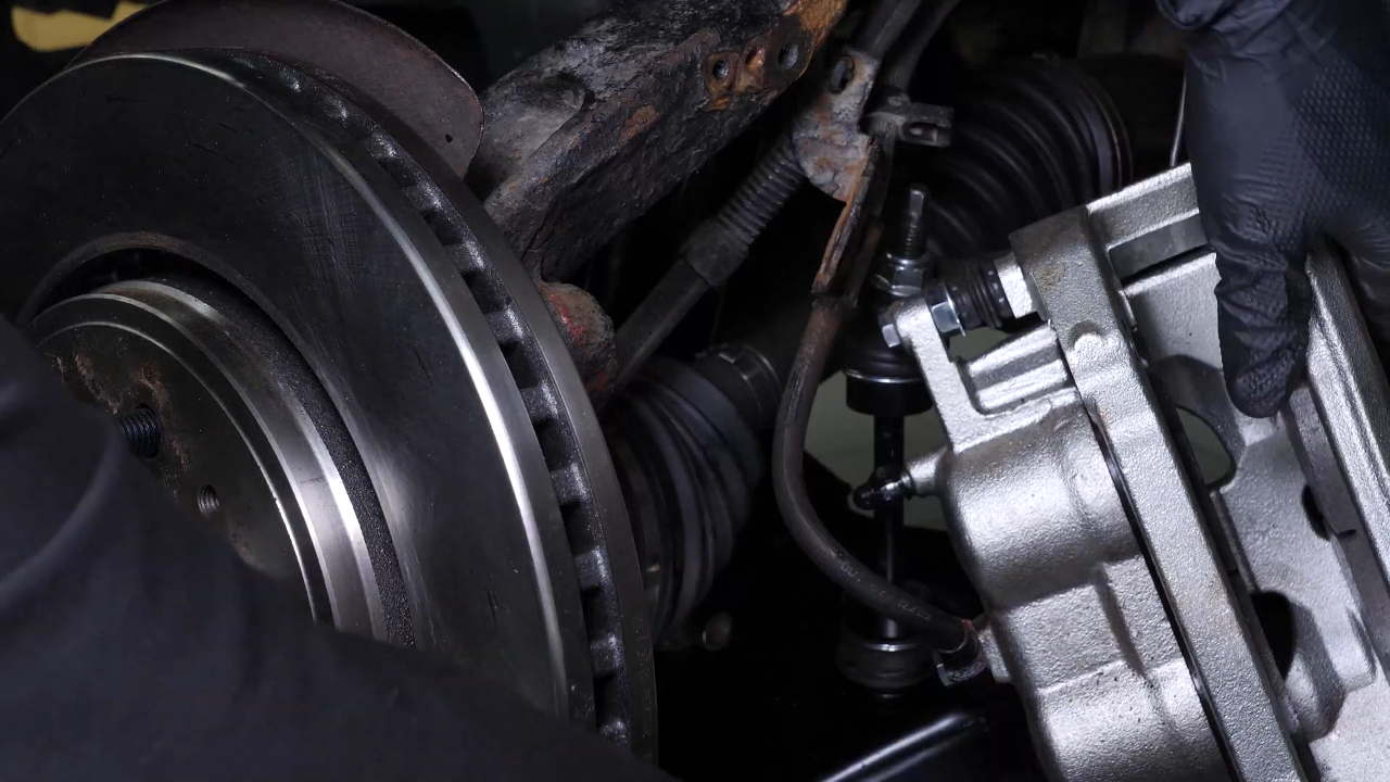
Start by attaching an iron thread to the vehicle body to hold it together when it is removed. Then using a ratchet and a 21mm socket, unscrew the two screws from the caliper mount. Then attach it to the previously installed iron thread.
Chapter 7:
Remove the sway bar end link
Step 1/2
Disconnects the sway bar end link from the lower control arm. To do so, we recommend watching our video : “How to replace the sway bar end links Ford F-150?”
Chapter 7:
Step 2/2
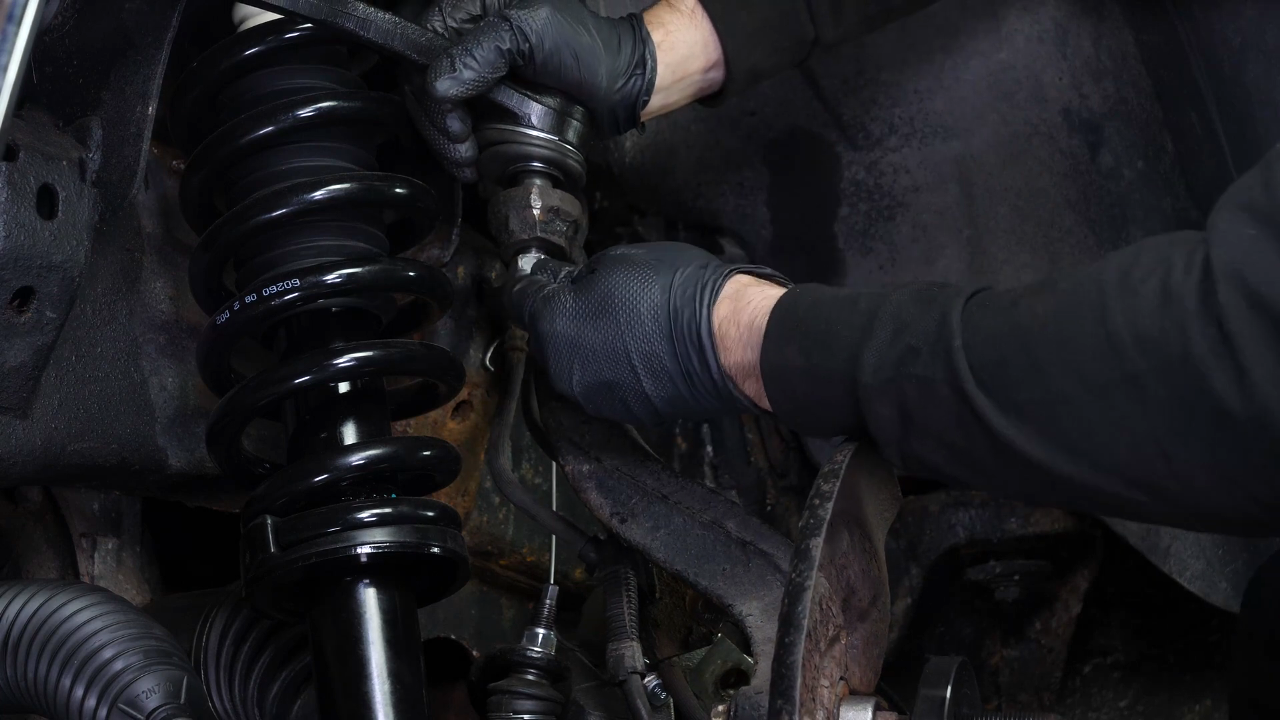
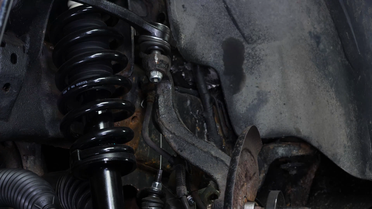
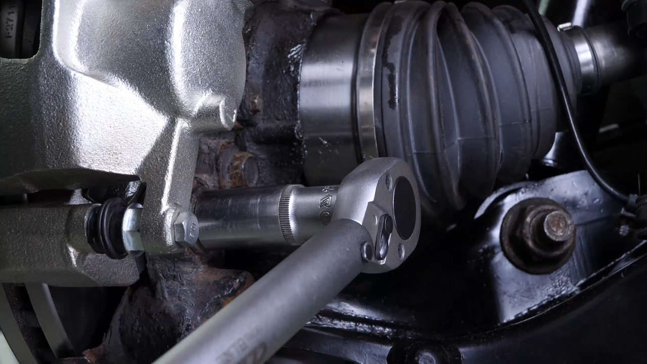
Using a ratchet and a 22mm socket, loosen the upper control arm ball joint nut and unscrew it a few threads. Tap on the knuckle to release the ball joint.
Chapter 8:
Remove the outer tie rod
Step 1/1
Using a socket wrench and a 21mm socket, unscrew the locknut on the outer tie rod and remove some of the holding nuts. To do so, we recommend watching our video : “How to replace the outer tie rod Ford F-150?”
Chapter 9:
Remove various components
Step 1/2
Complete the removal of the upper control arm ball joint nut.
Chapter 9:
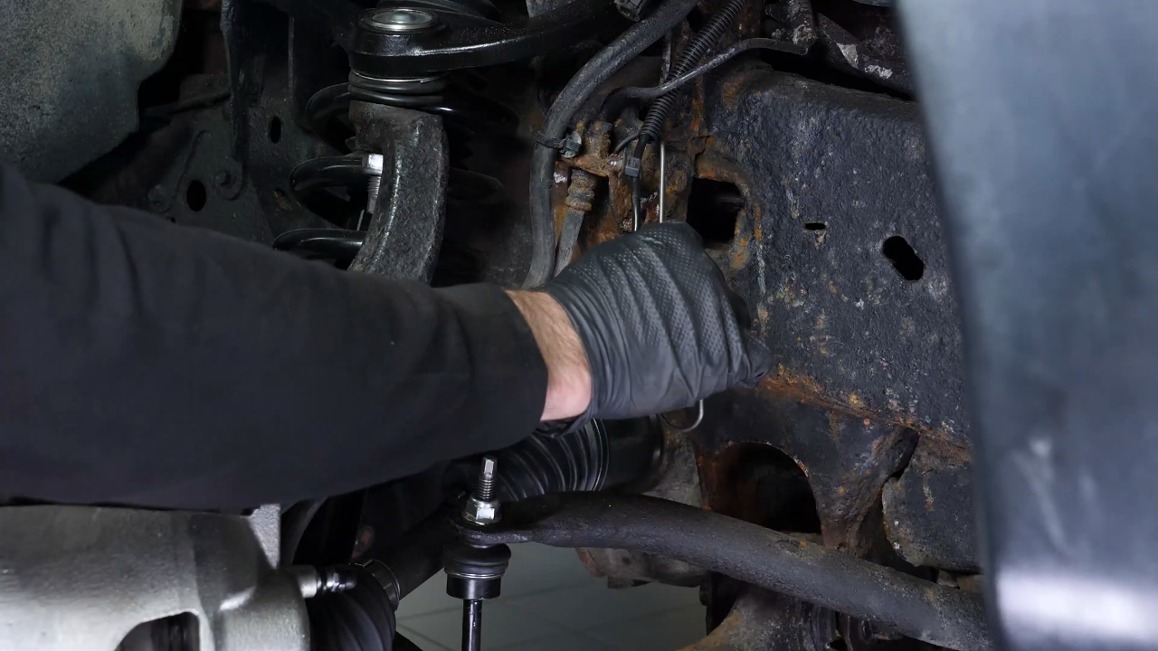
Step 2/2
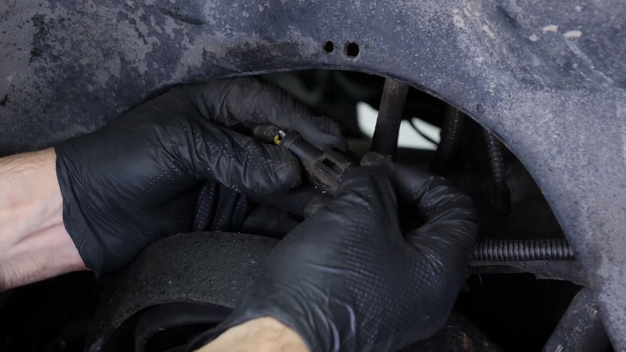
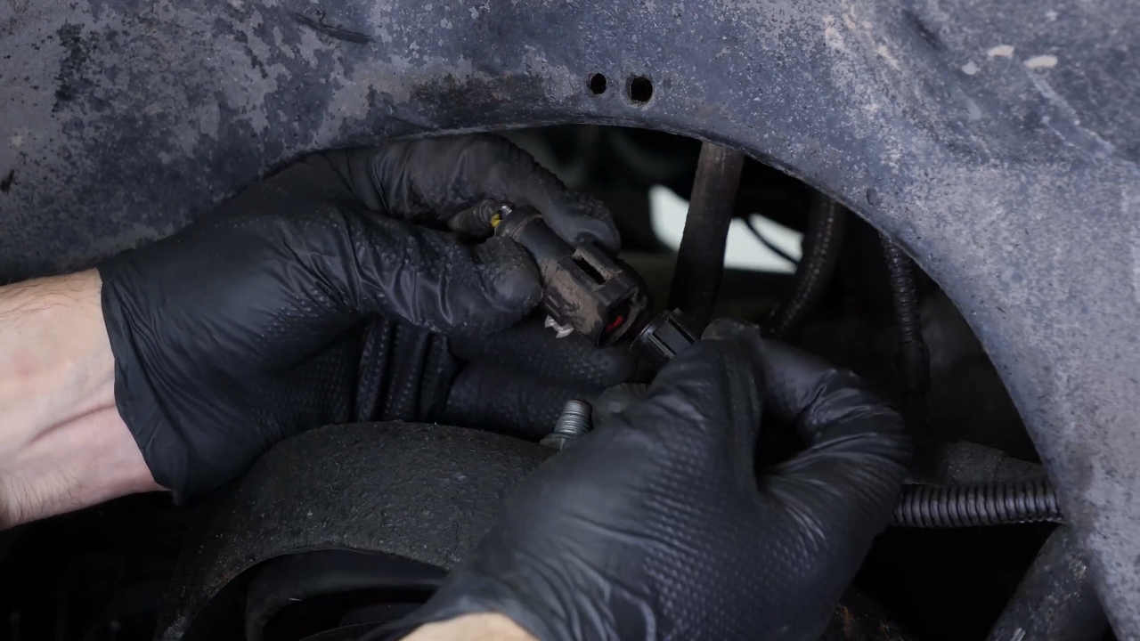
Disconnect the vacuum lines from the hub lock actuactor. Then remove the ABS sensor cable.


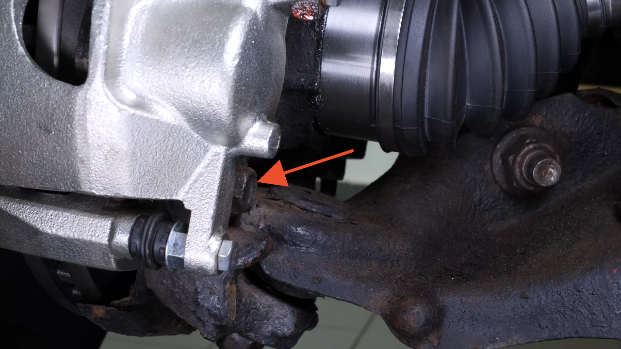
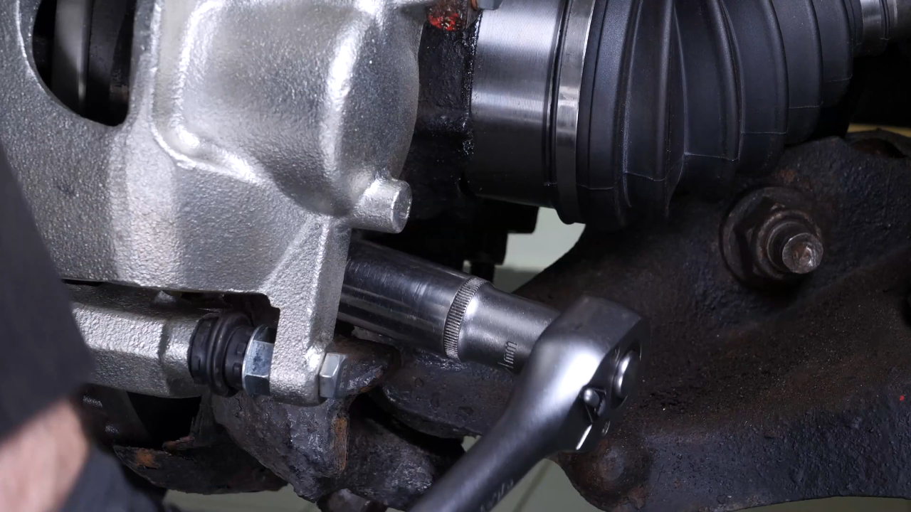
Chapter 10:
Remove the control arm ball joint
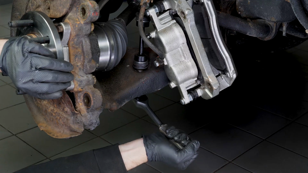
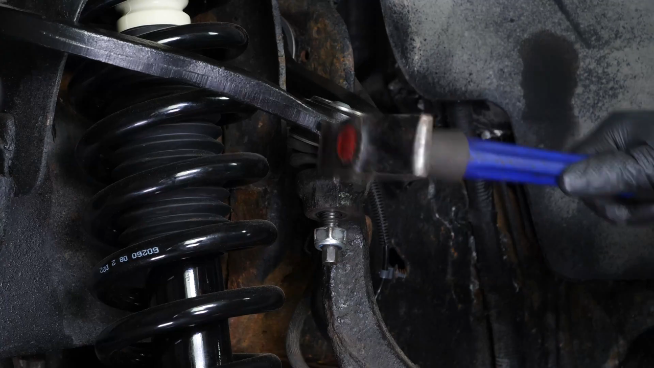
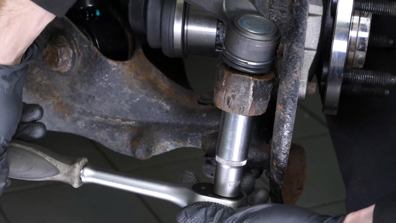
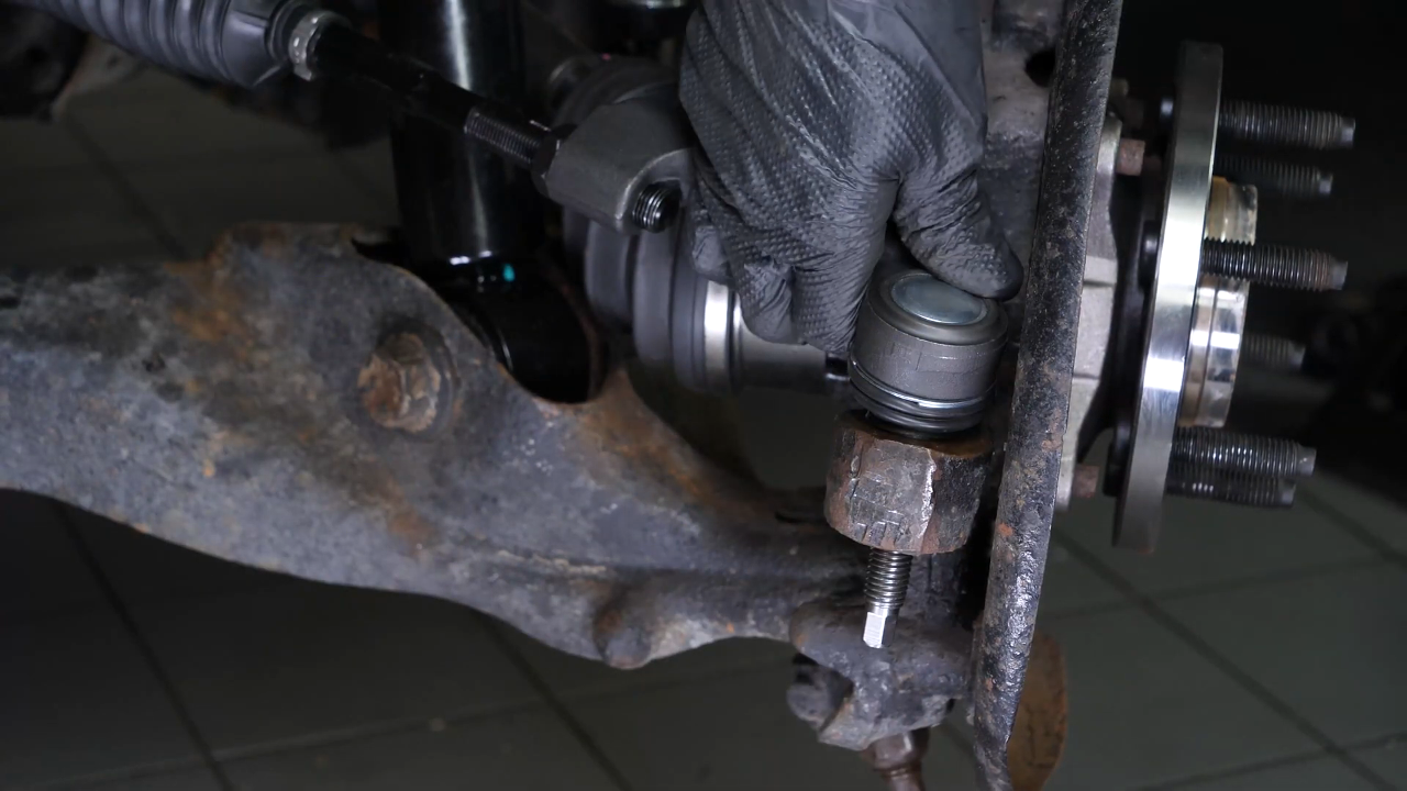
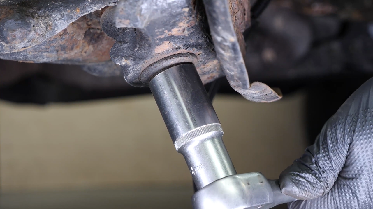
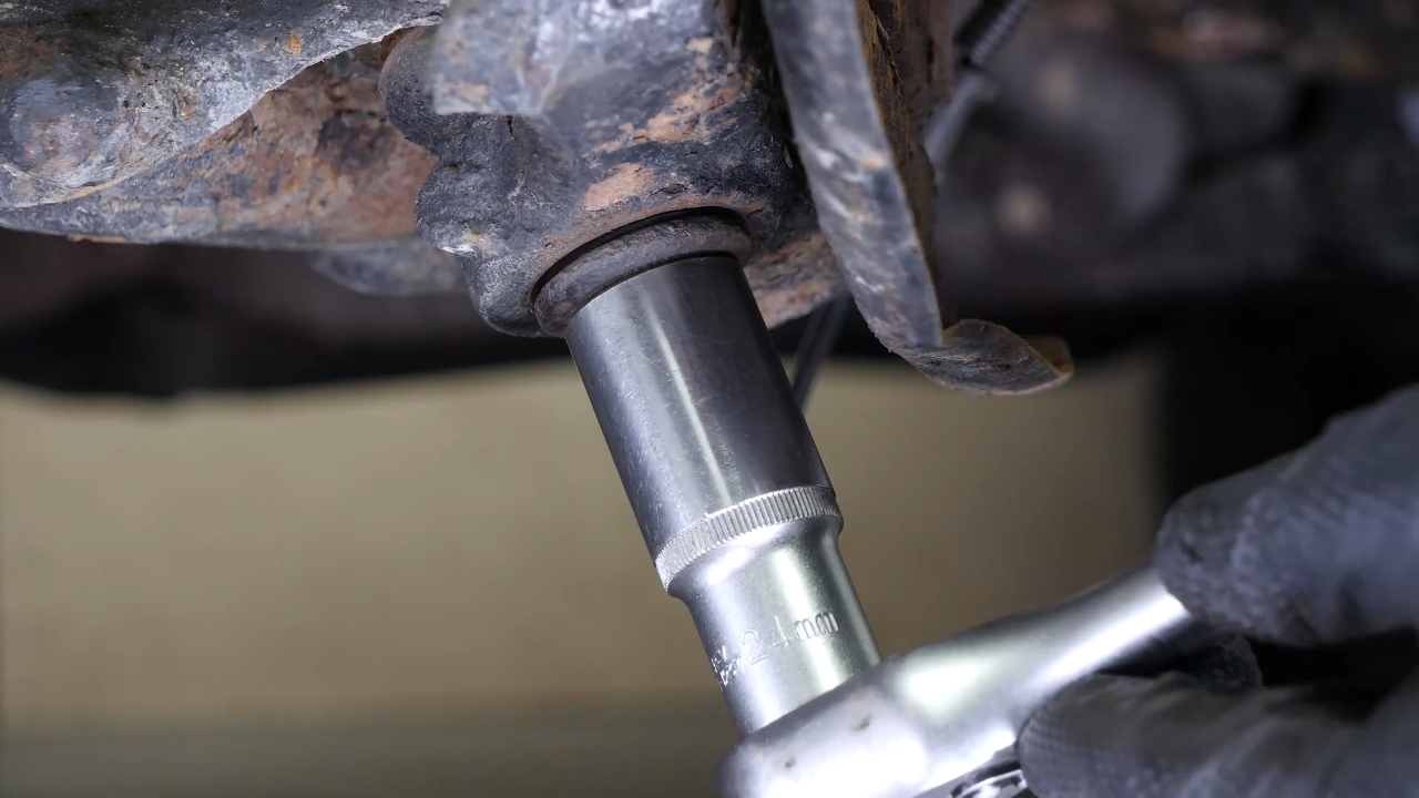
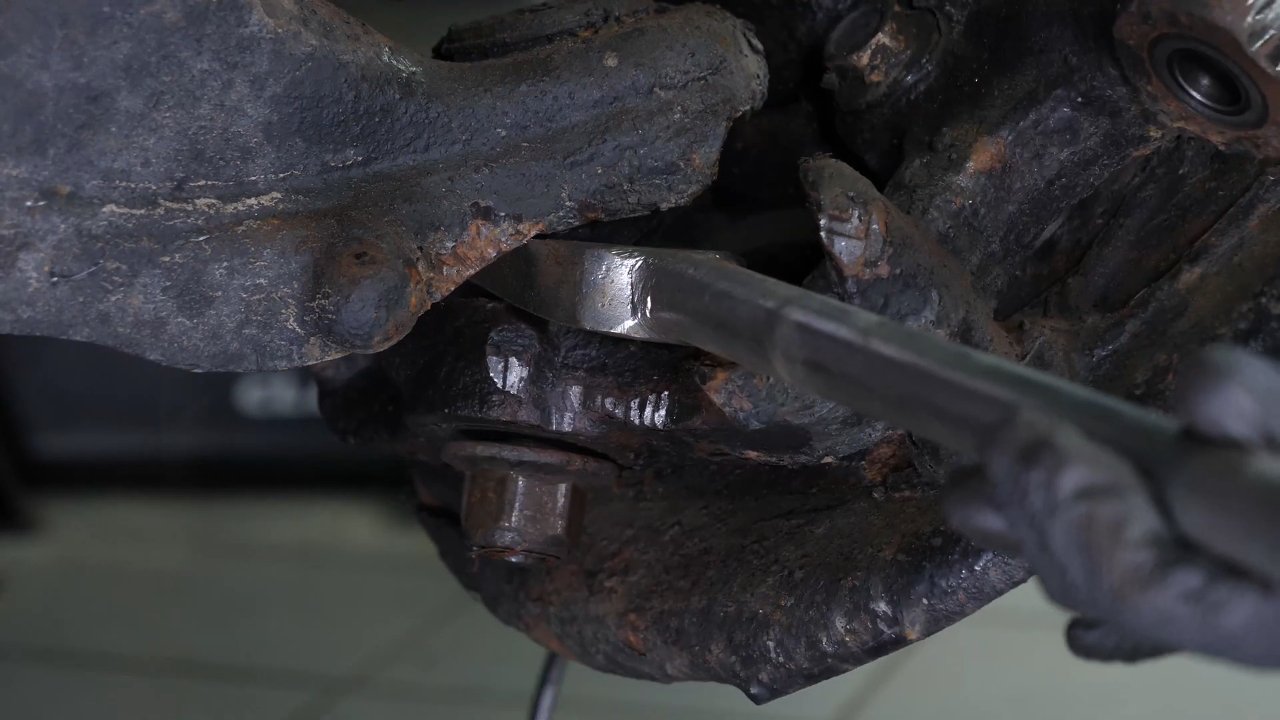
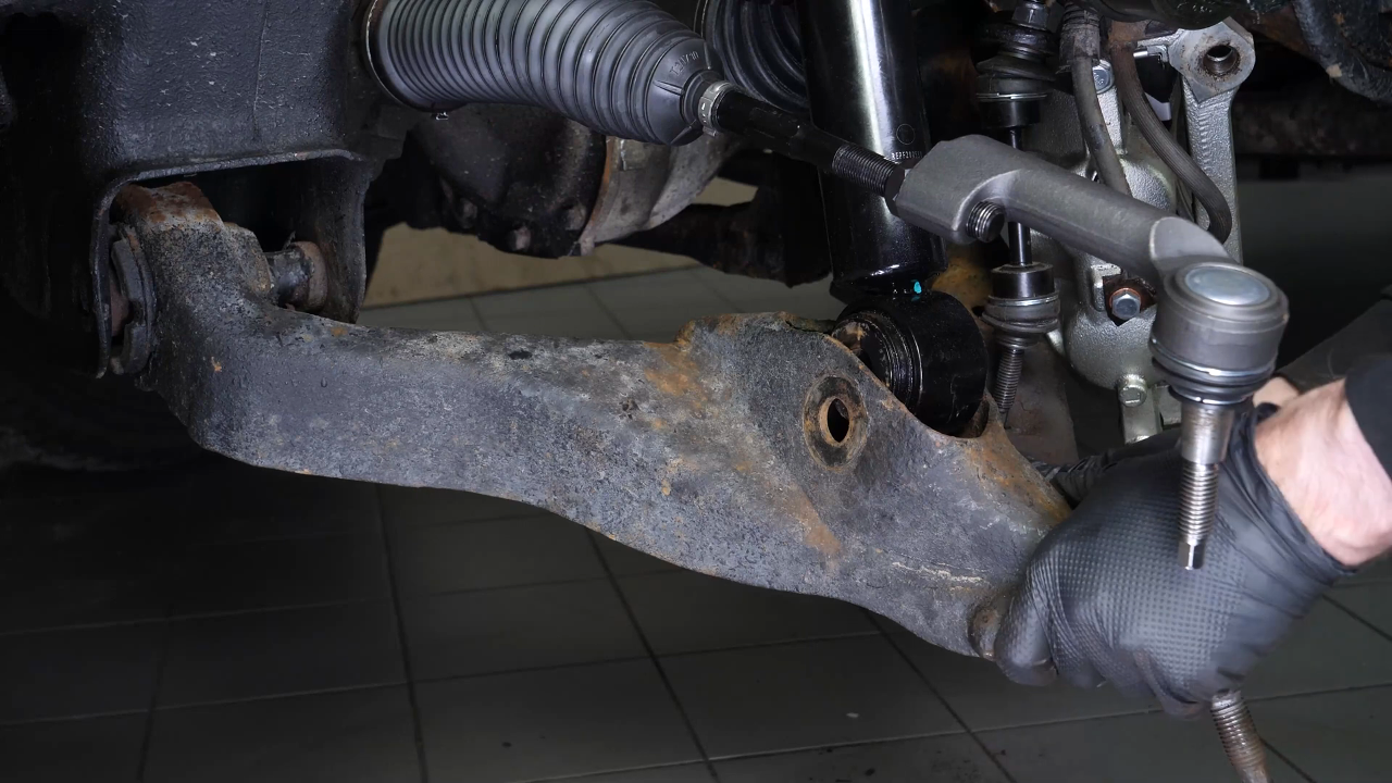
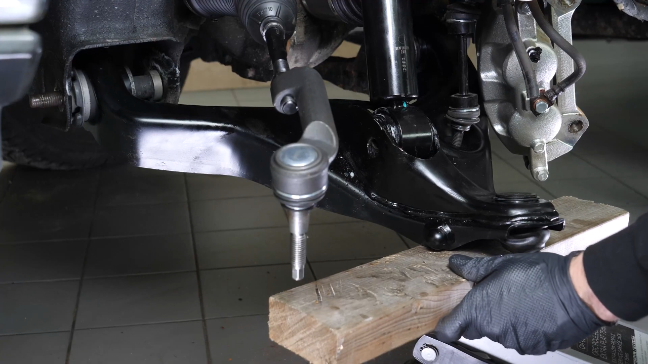
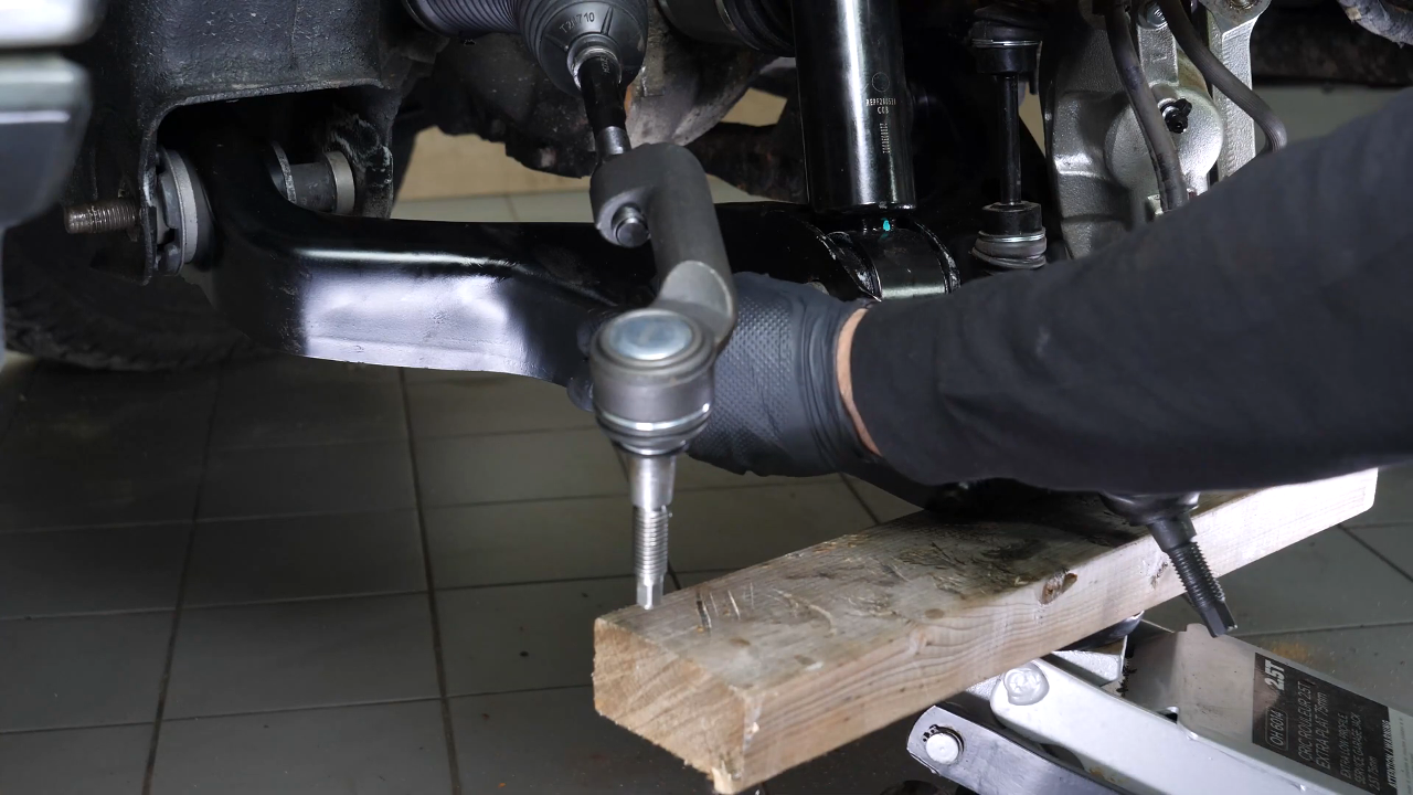
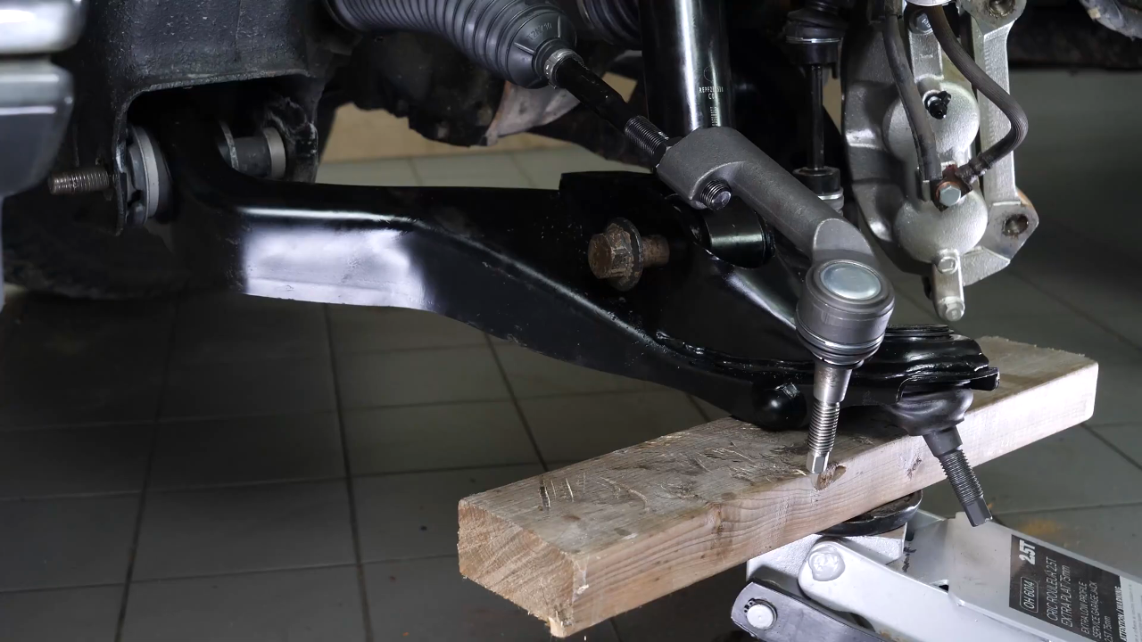
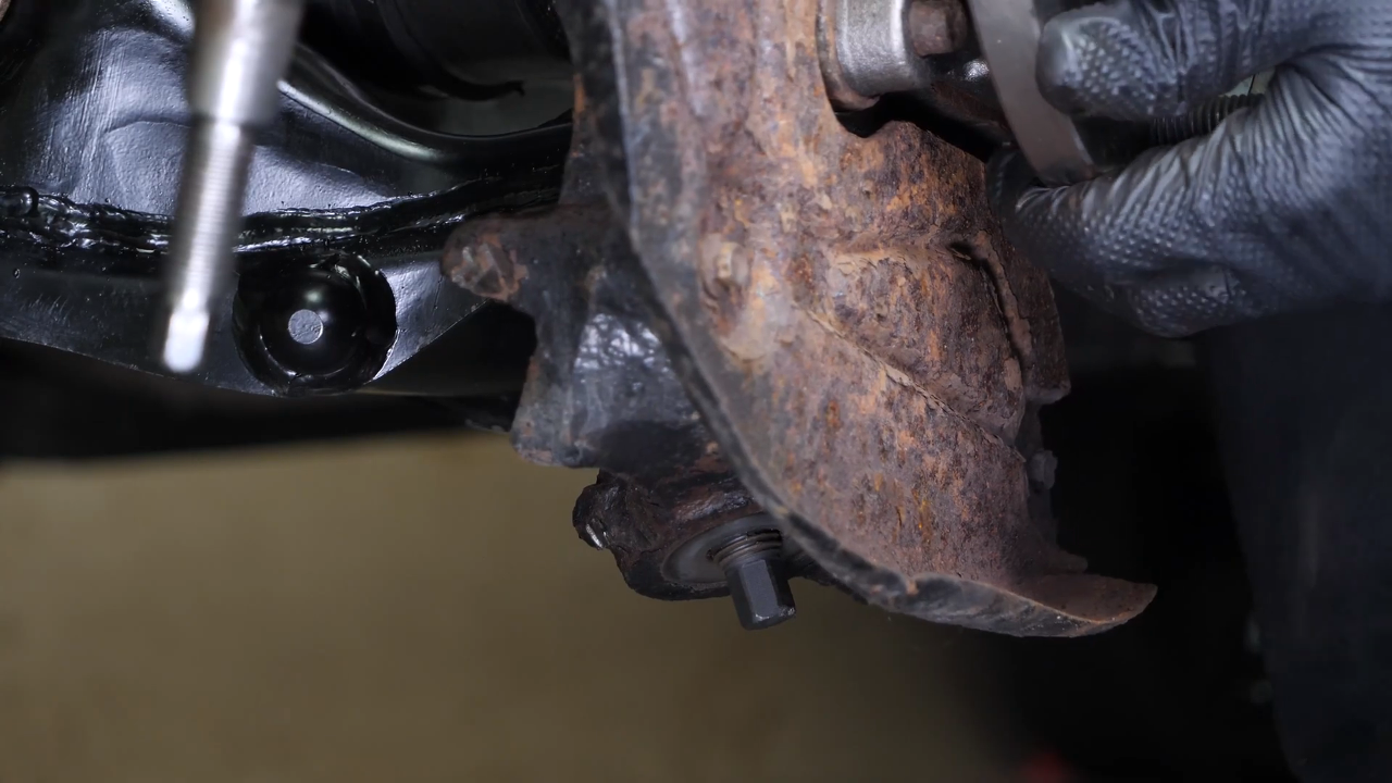
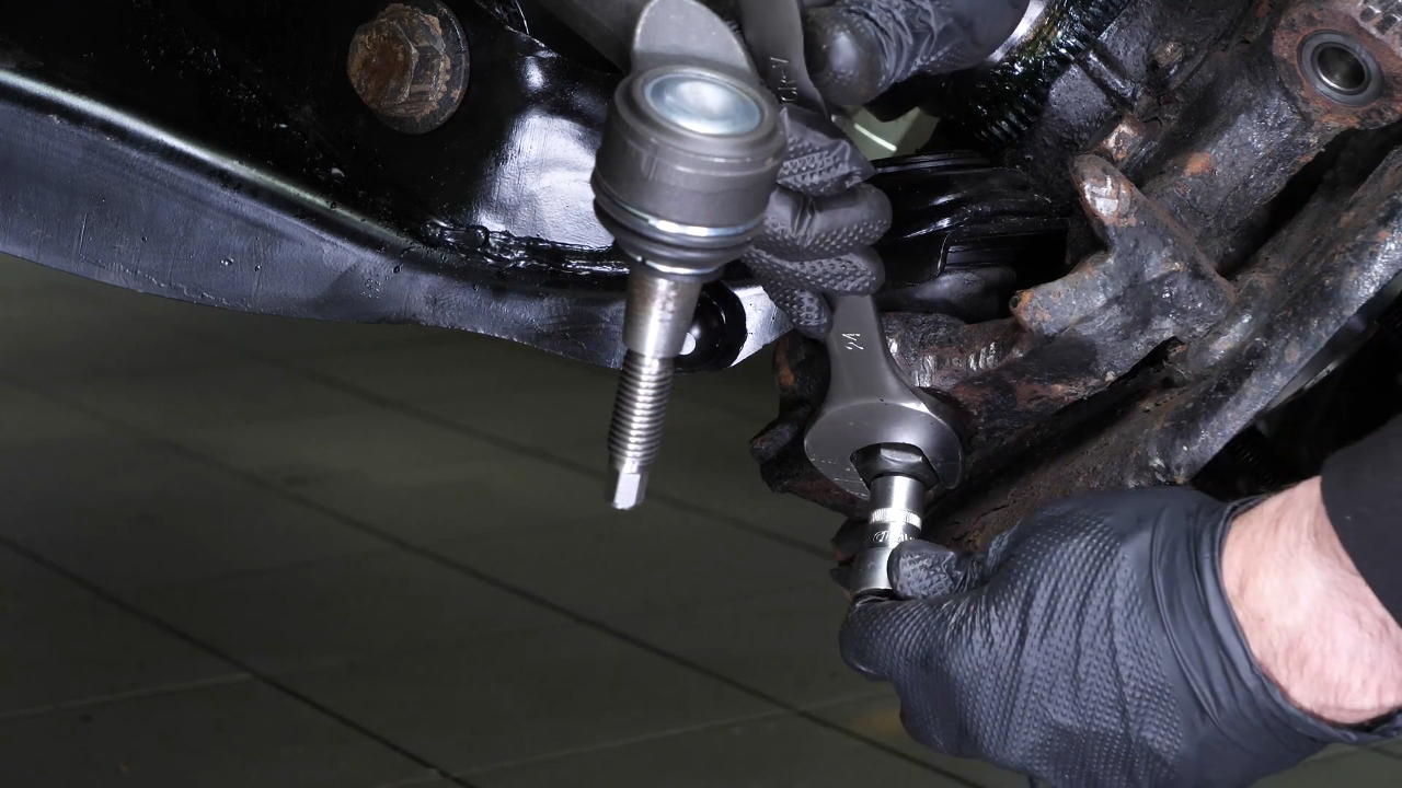
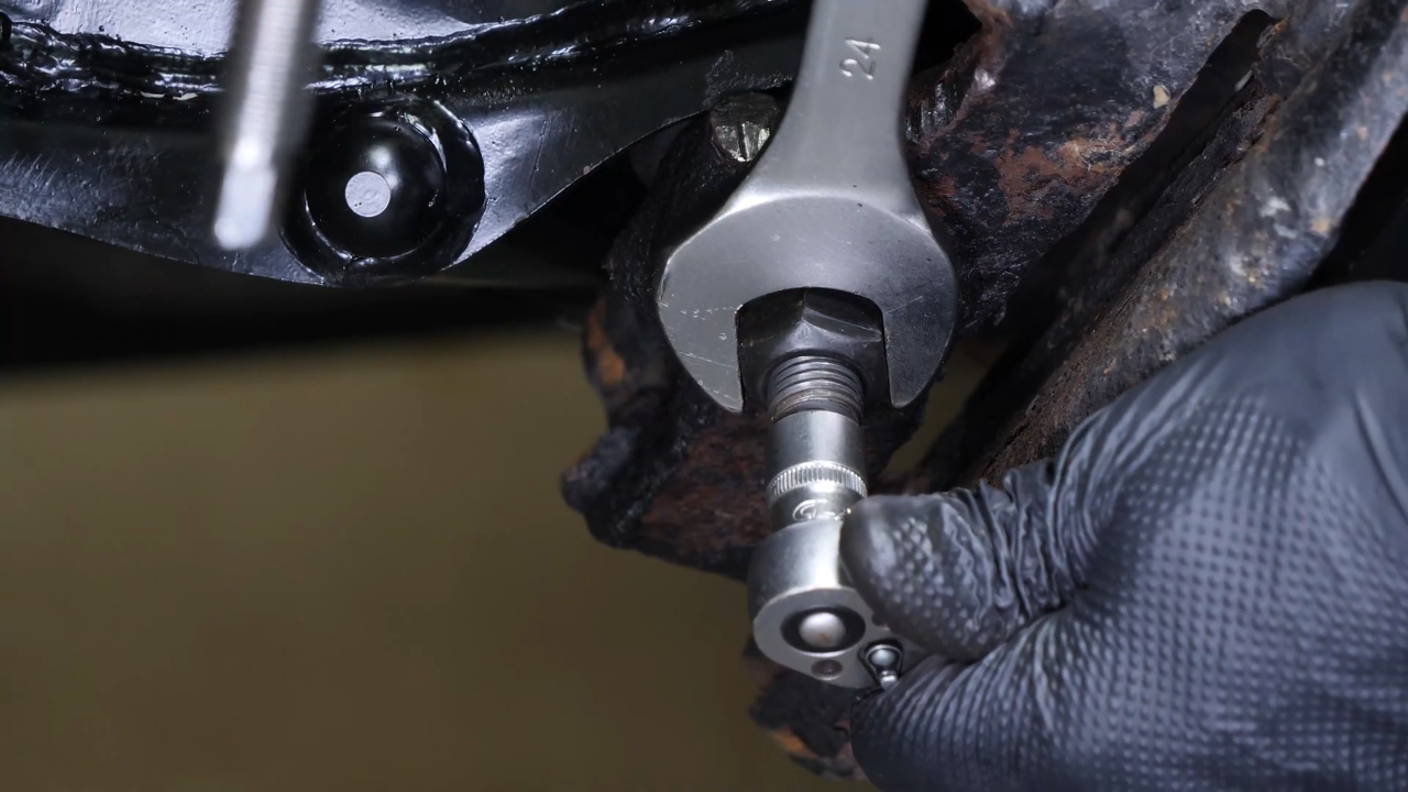
Step 1/4
Unlock the lower control arm ball joint nut using a ratchet and a 24mm socket, and unscrew the nut a few threads. Tip: to avoid everything rotating when unscrewing, reinsert the outer tie rod into its knuckle. Remove the outer tie rod.
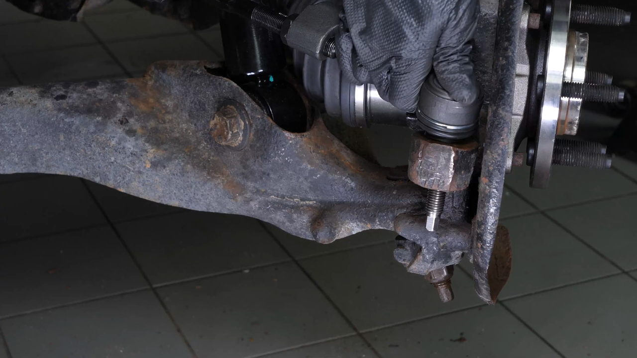
Chapter 10:
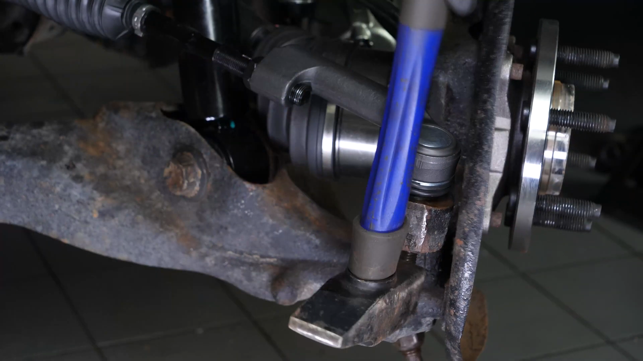
Step 2/4
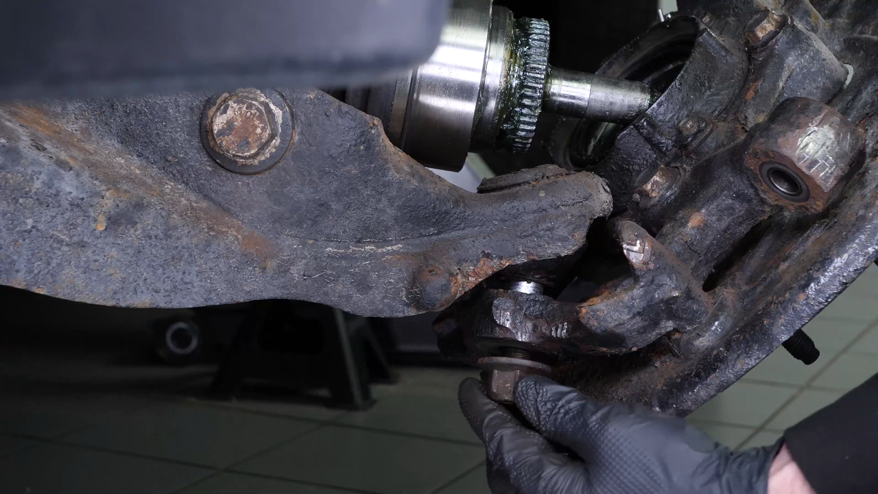
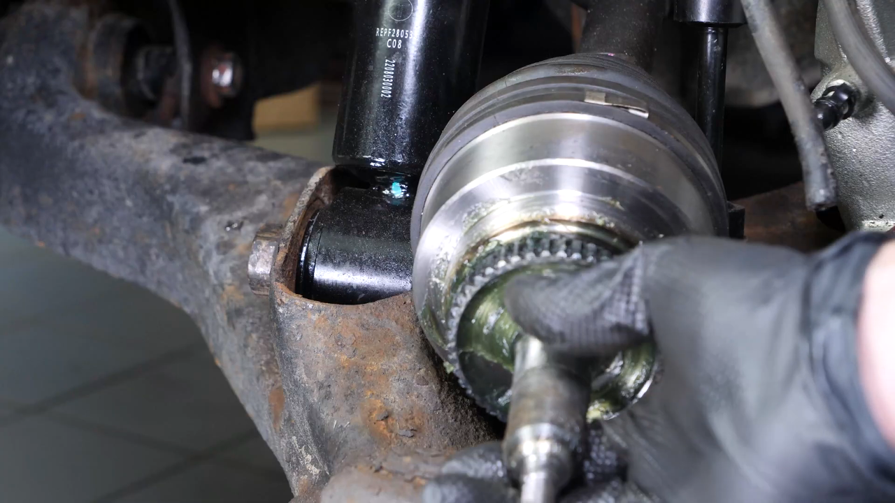
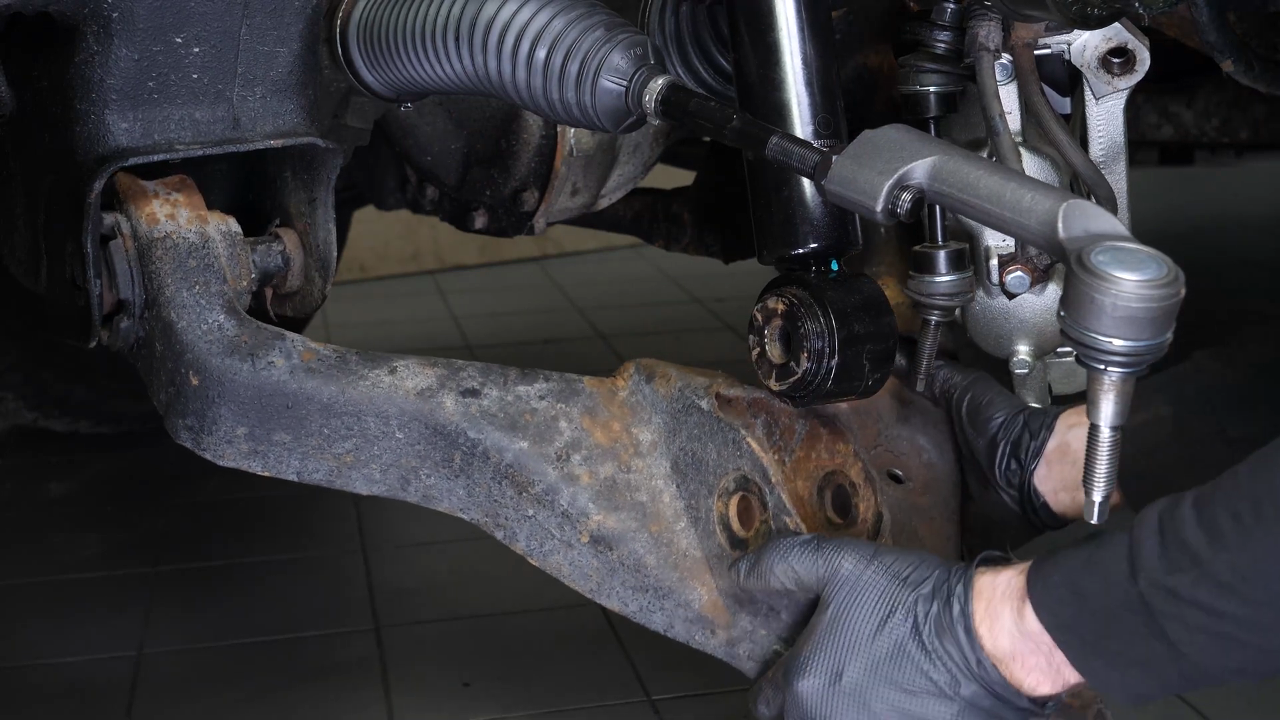
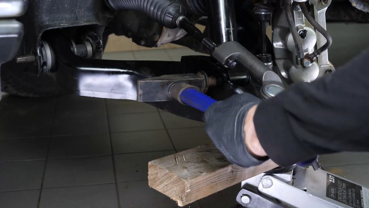
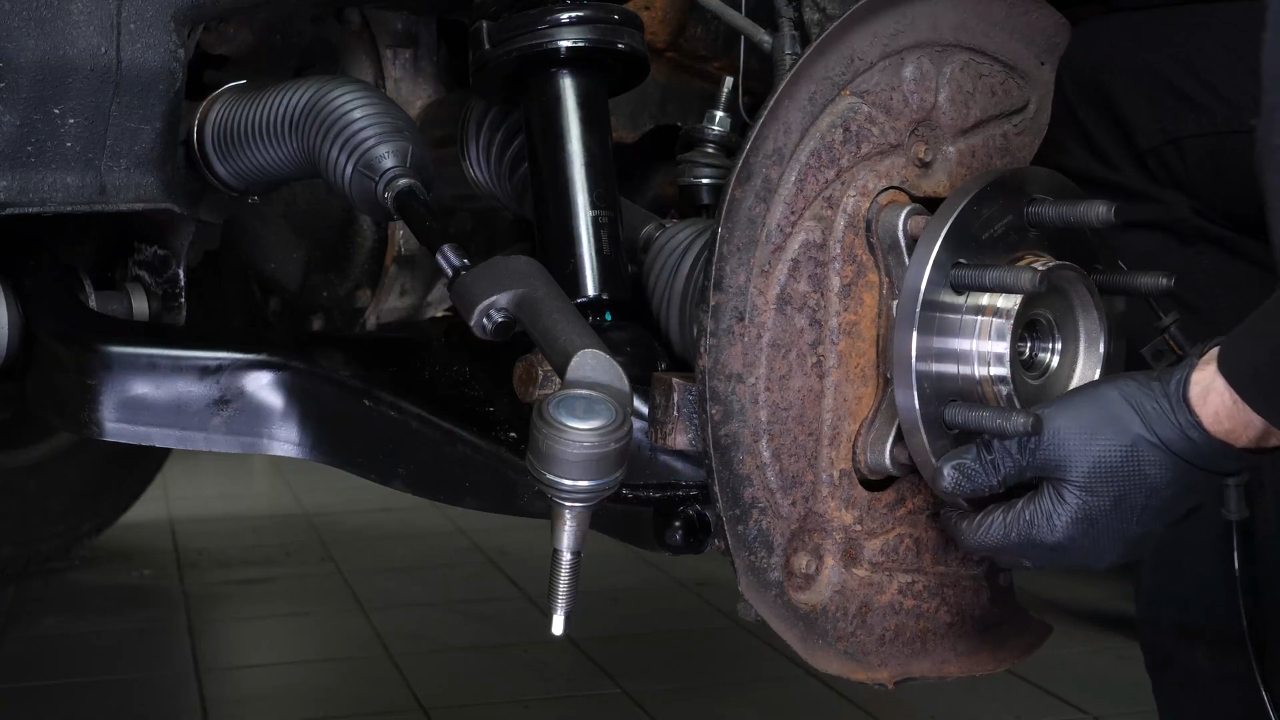
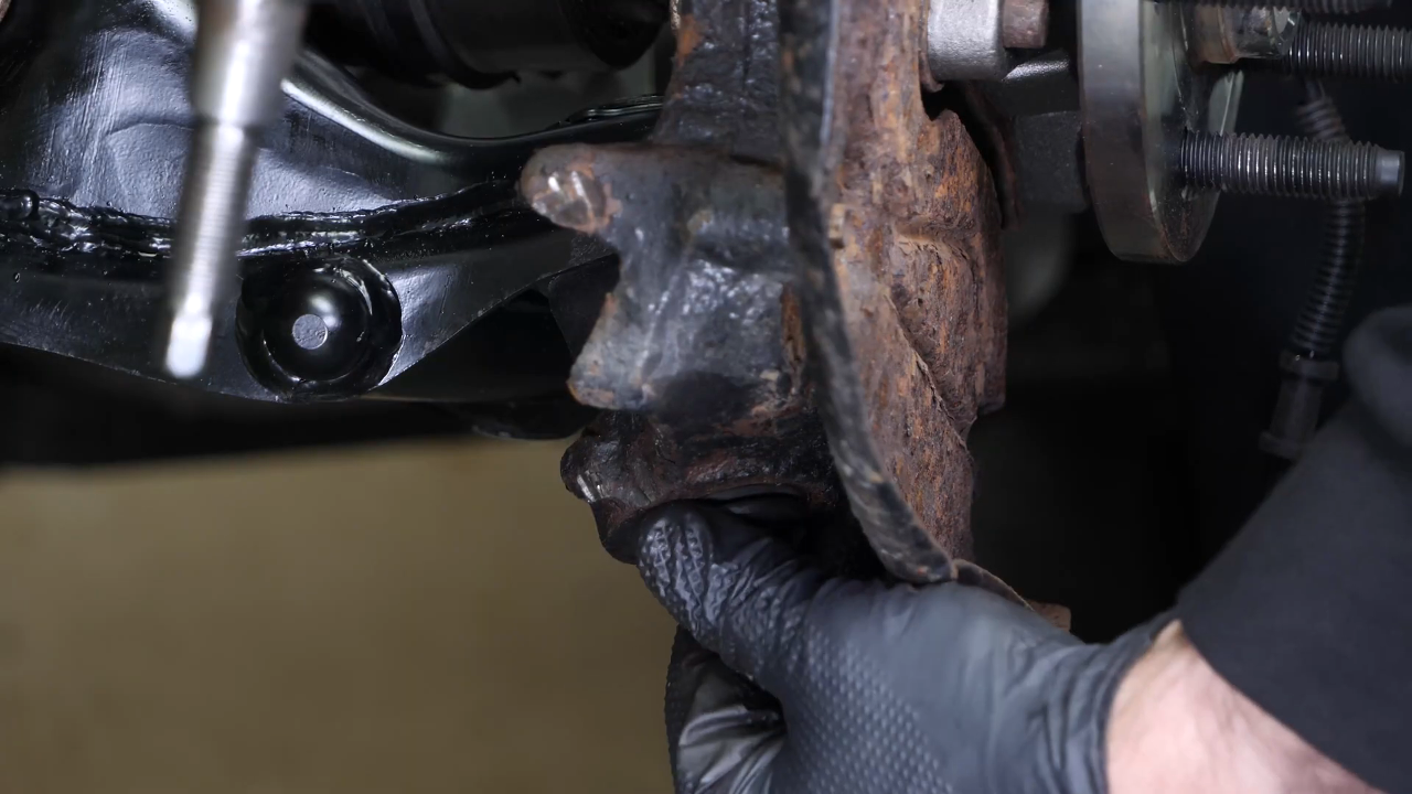
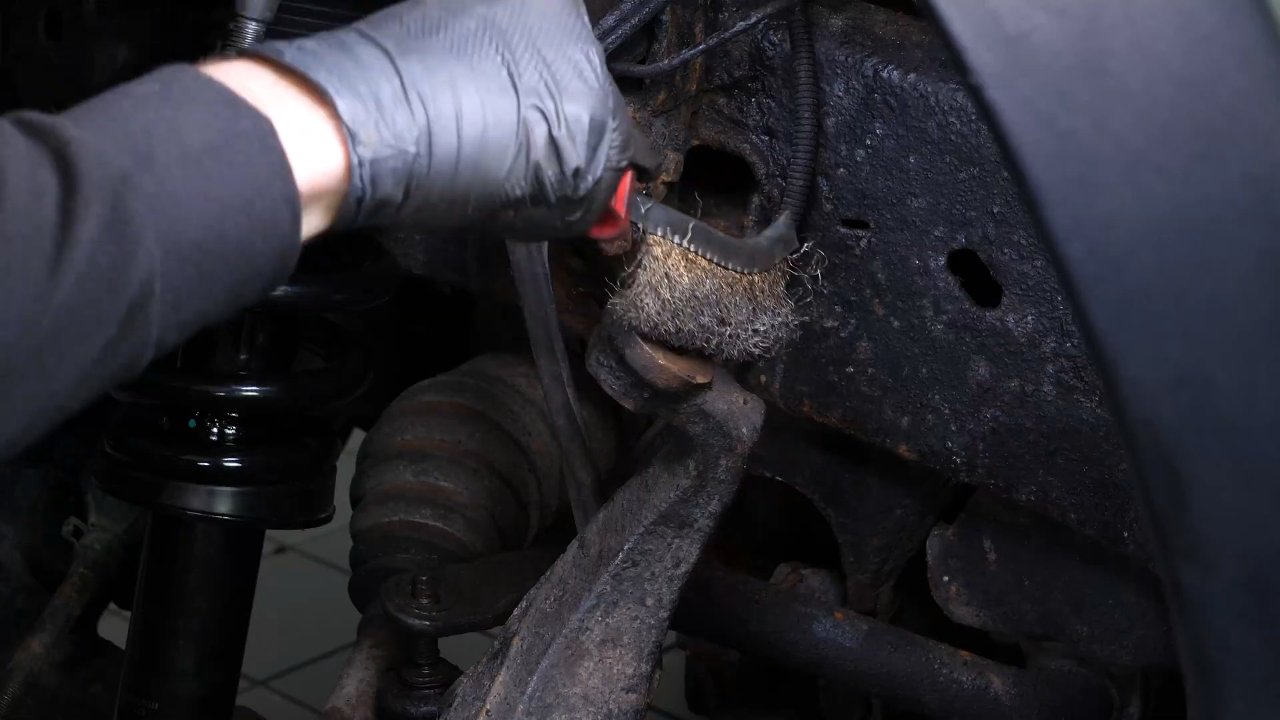
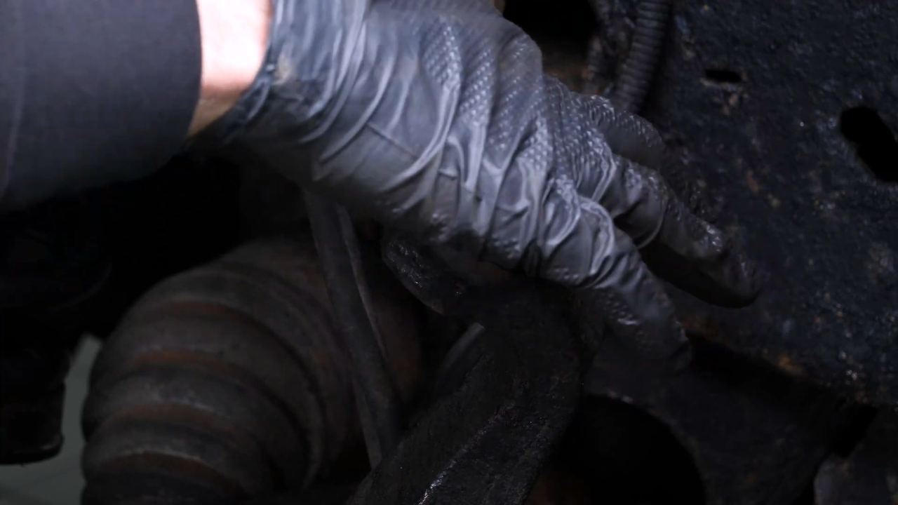
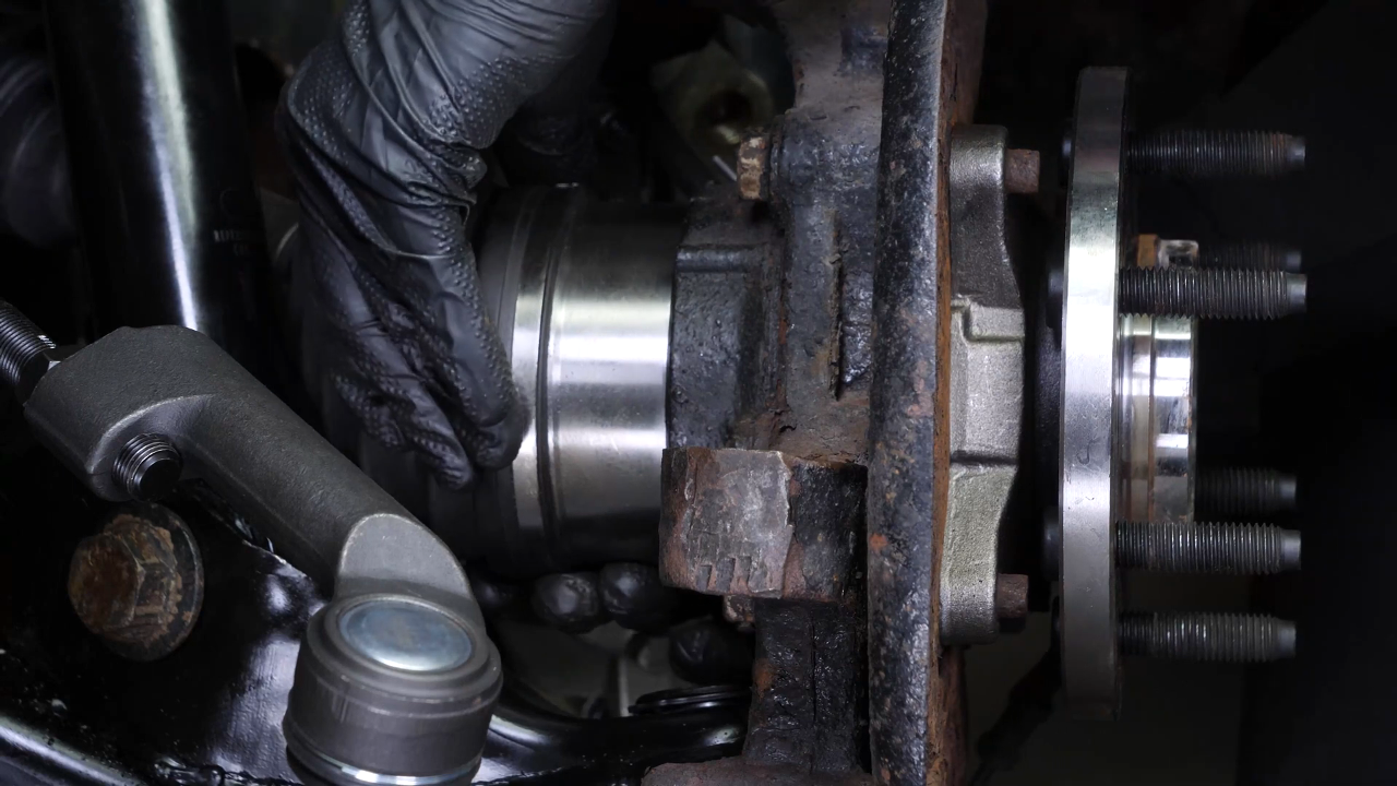
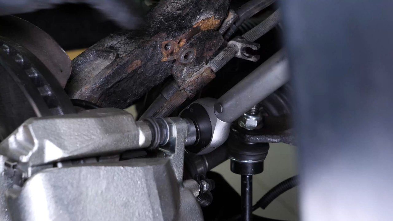
You can now disconnect the upper control arm from the wheel knuckle, so that you can remove the driveshaft from the hub. Using a forked ball joint puller, remove the ball joint from the wheel knuckle. Then lever the control arm ball joint completely out of its knuckle.
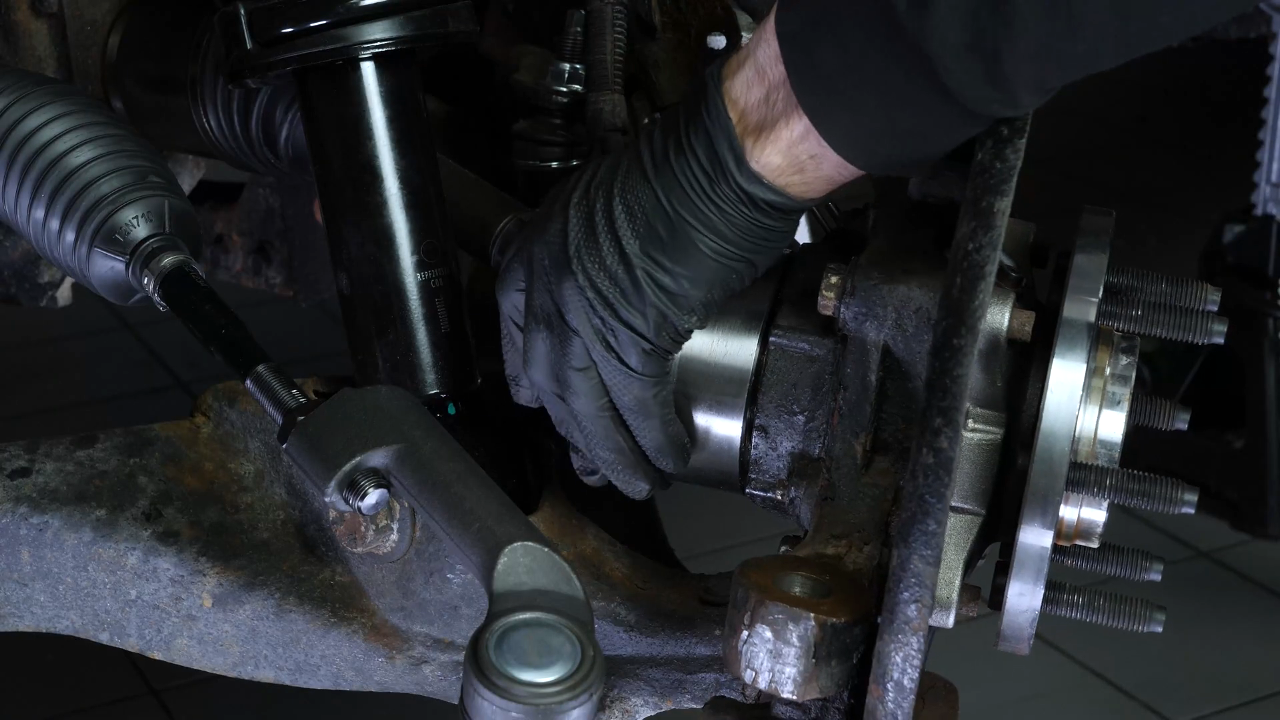

Chapter 10:
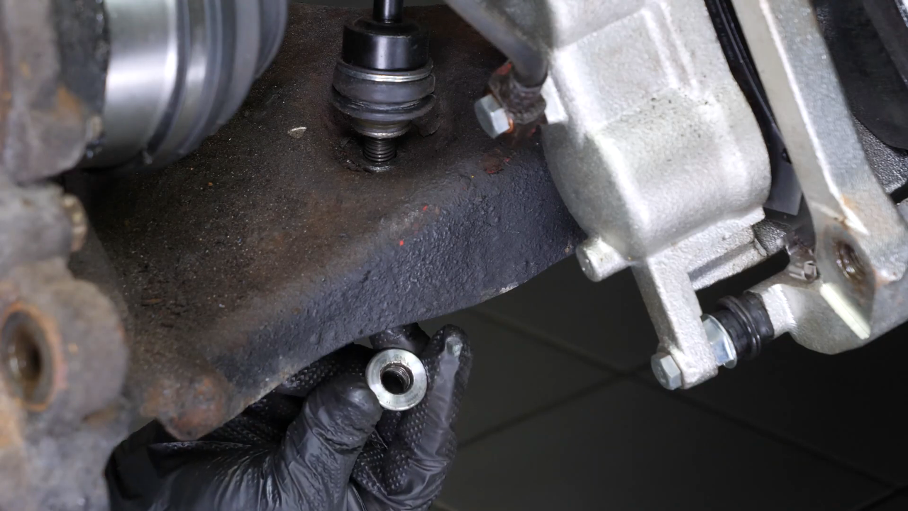
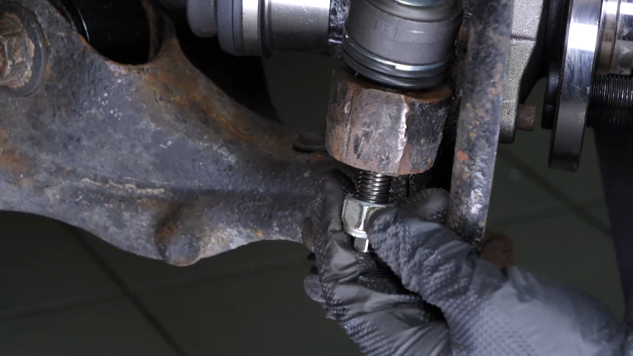
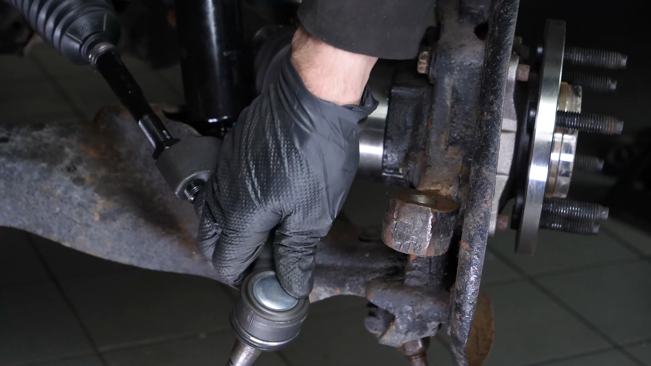
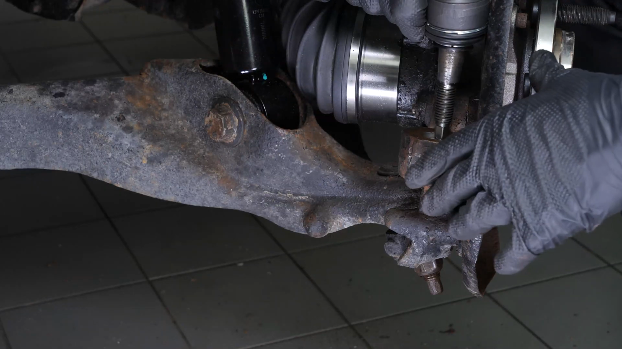
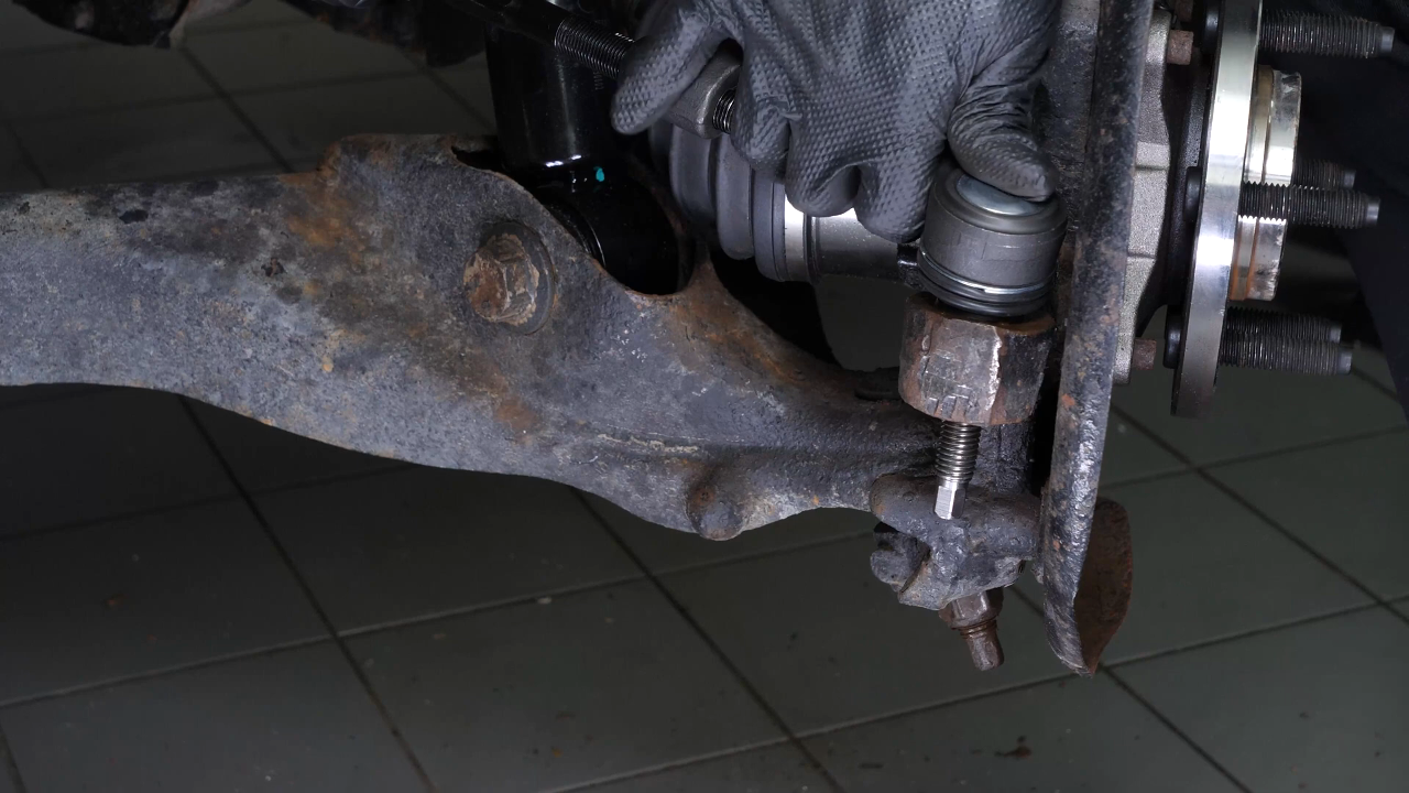
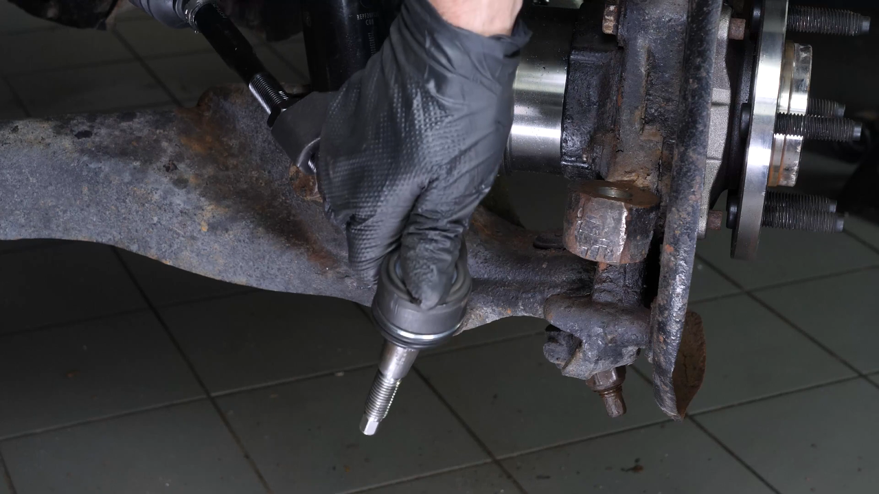
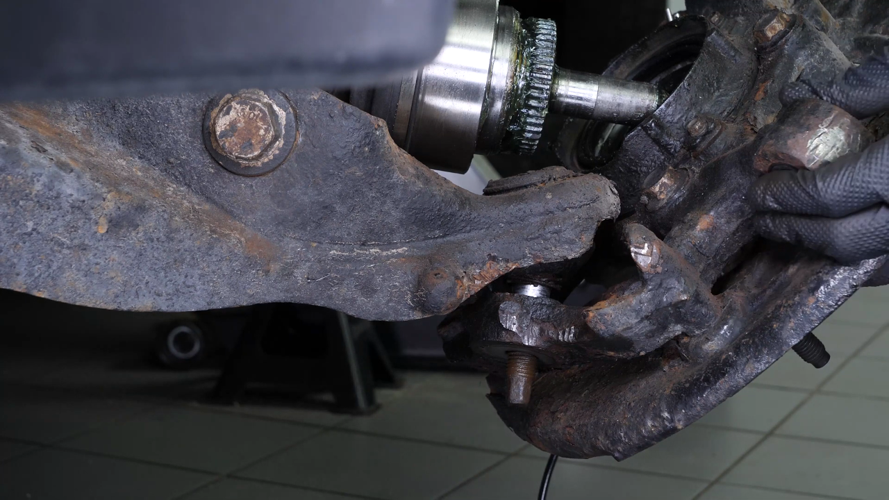
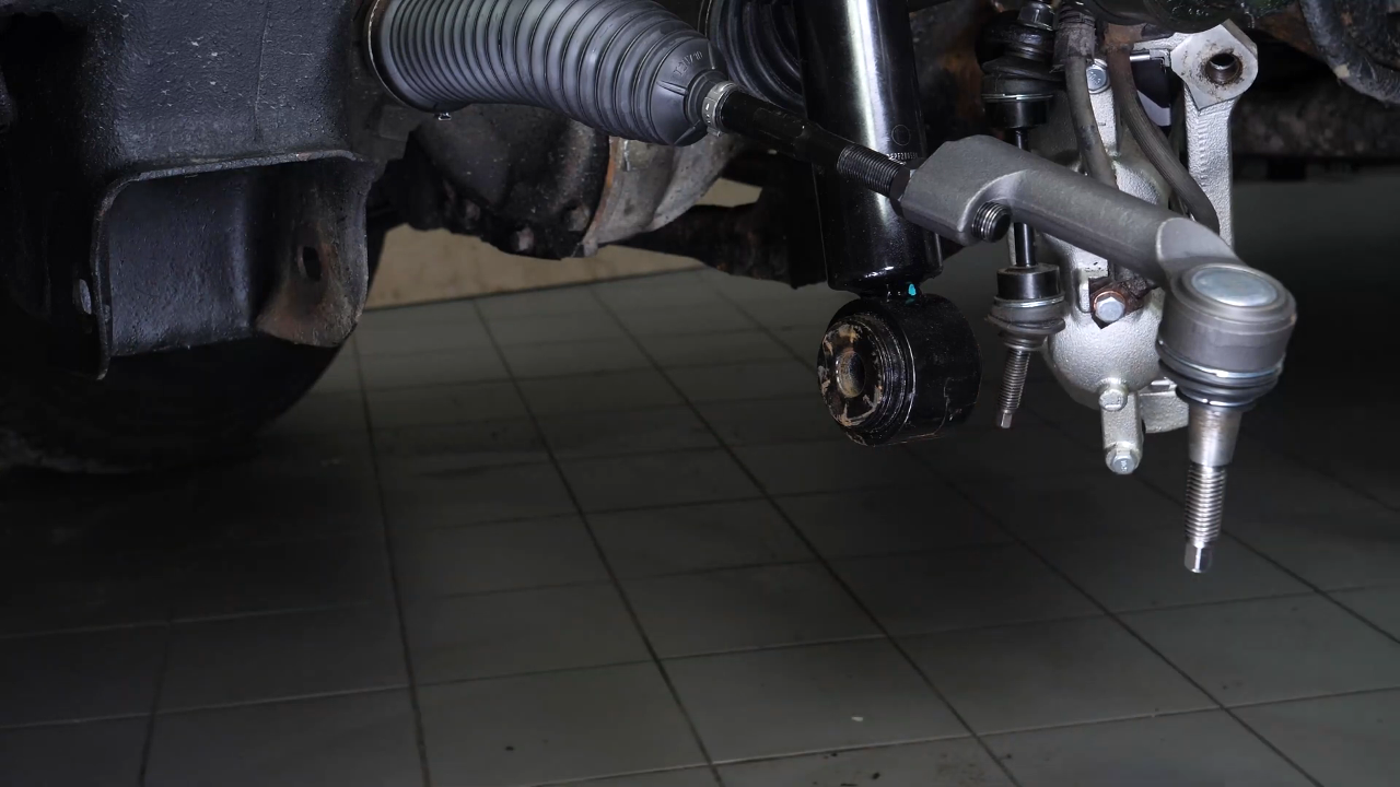
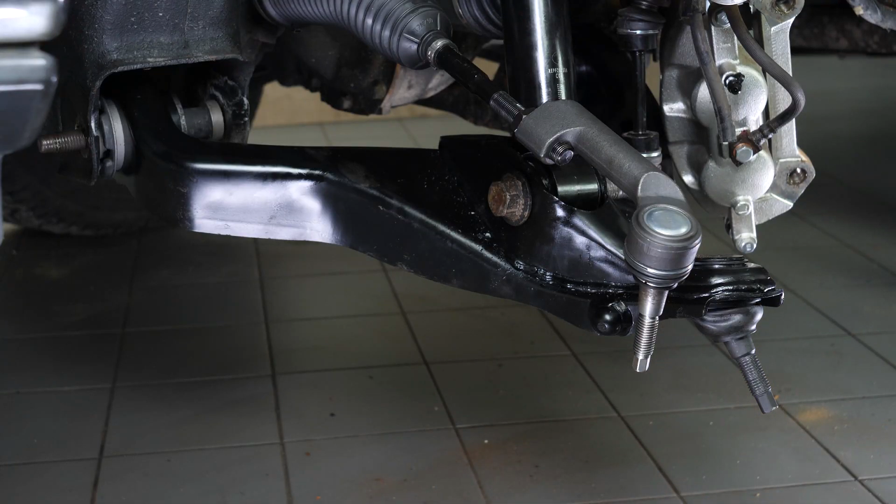
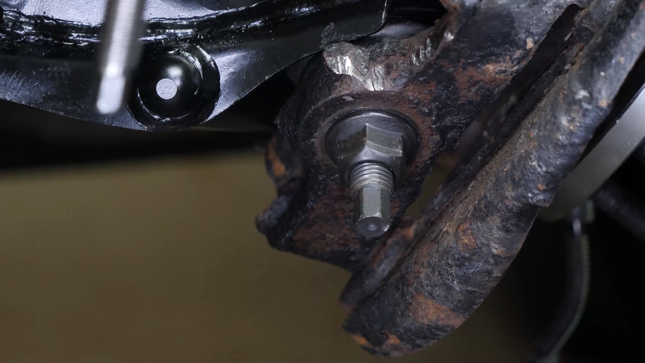
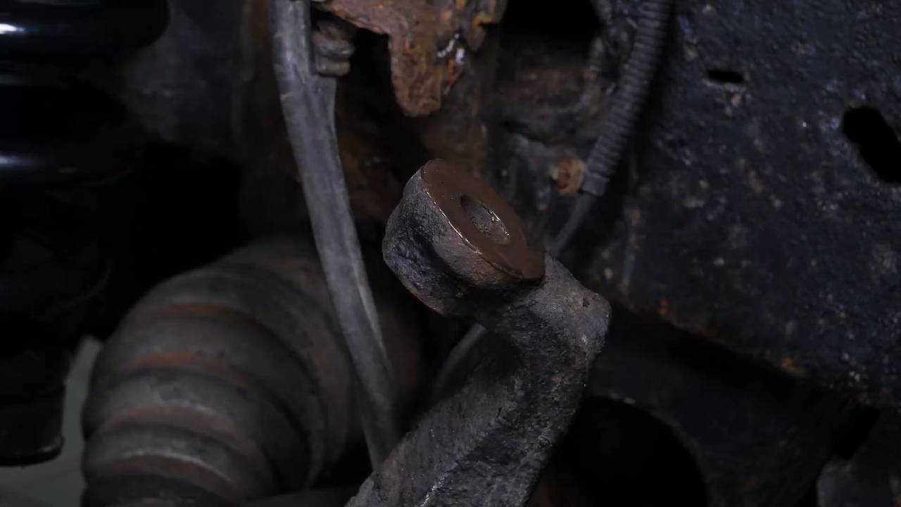
Step 3/4
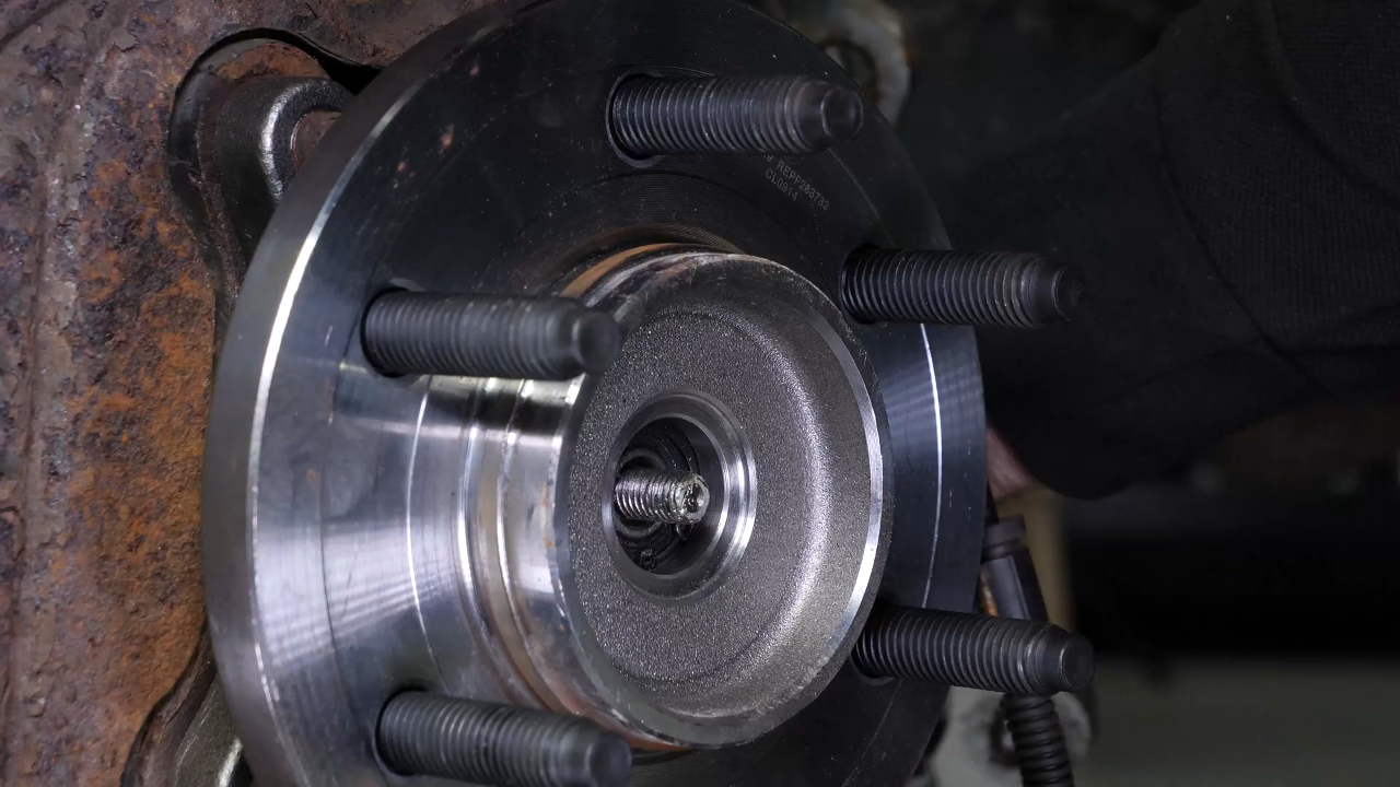
Then, while maintaining the wheel knuckle, finish unscrewing by hand. Extract the wheel knuckle.
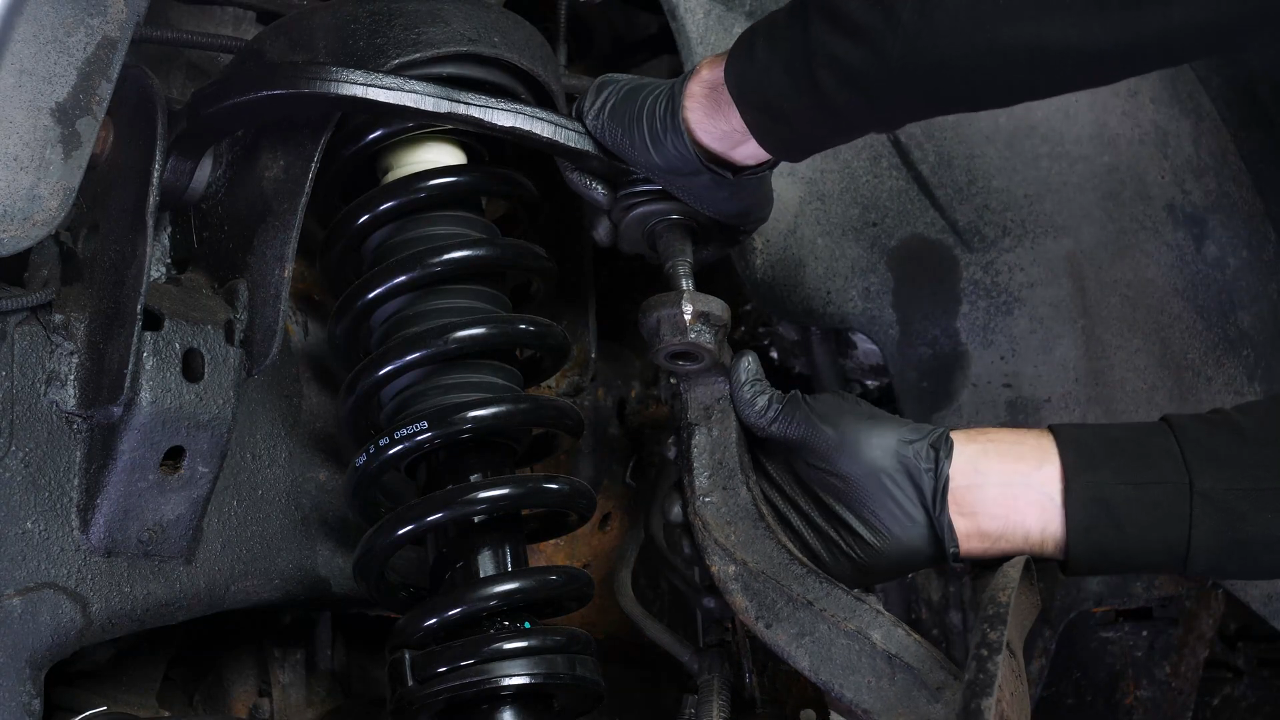
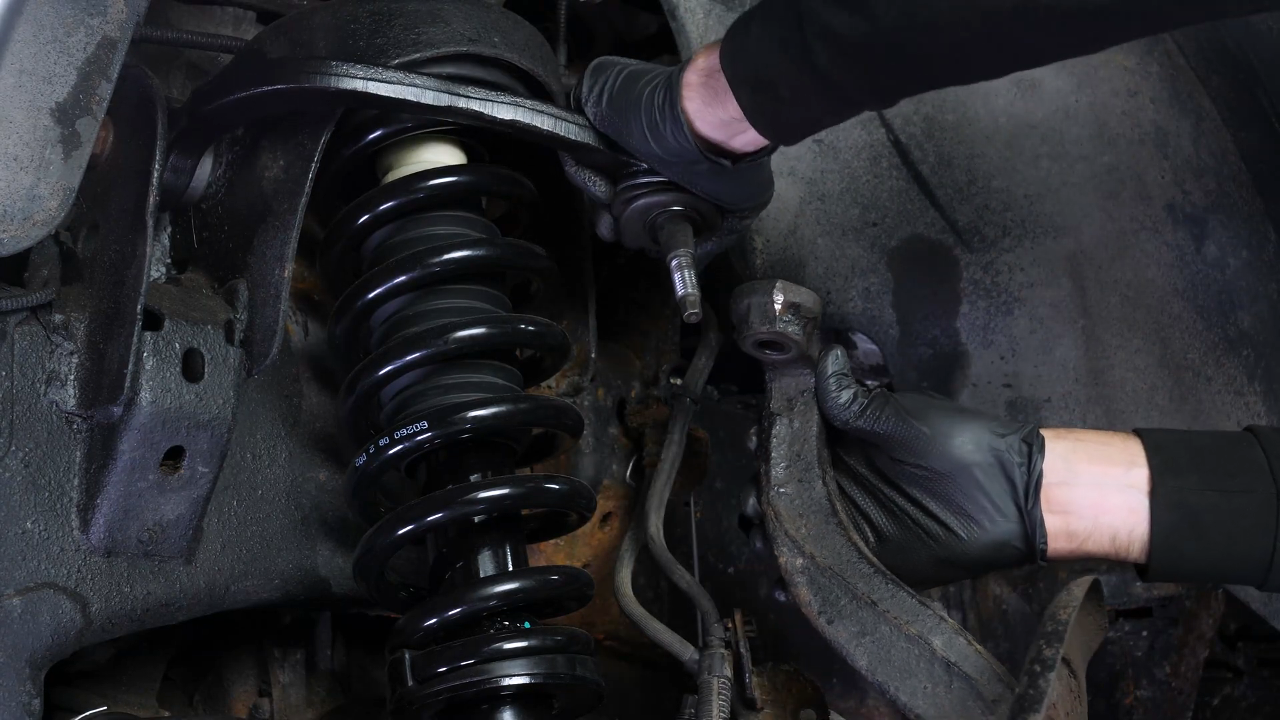
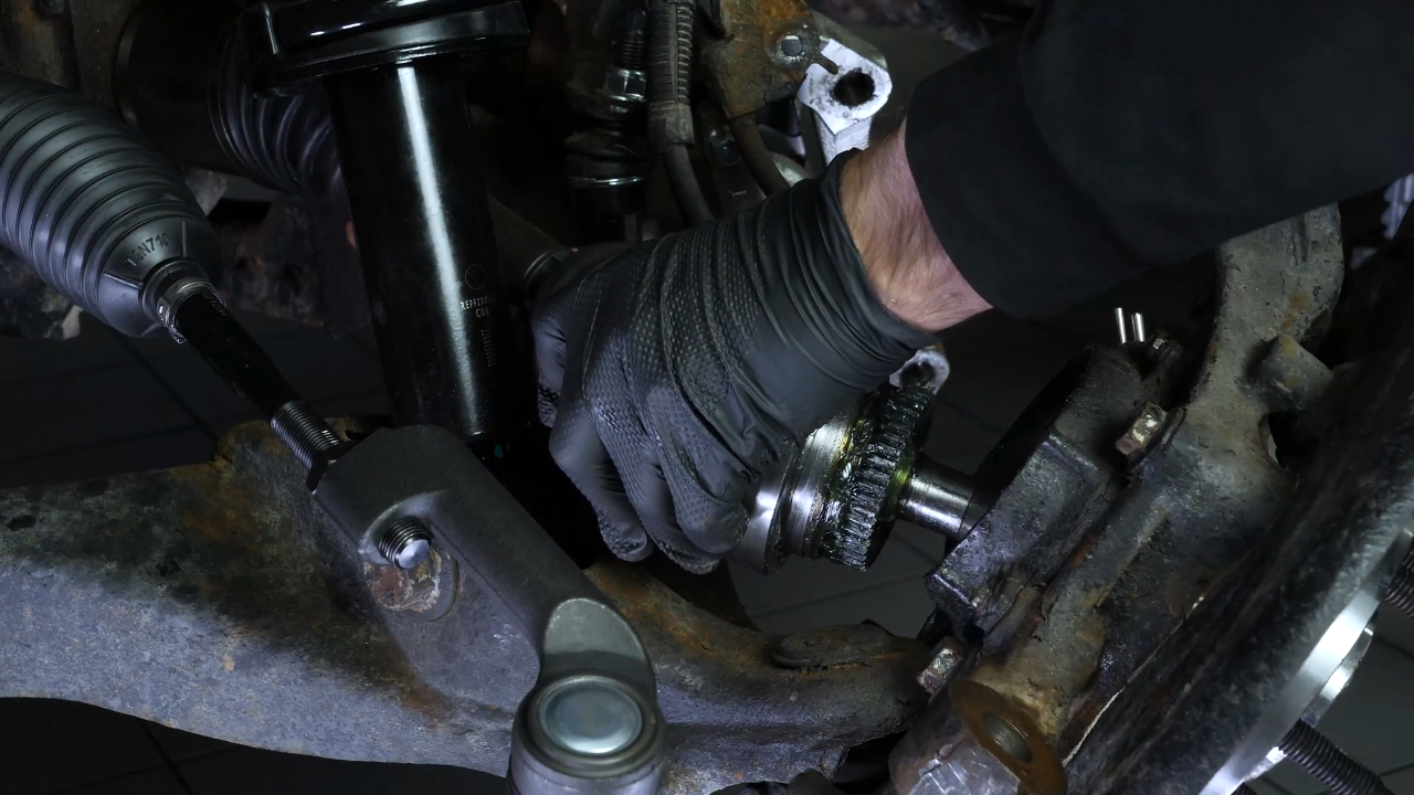
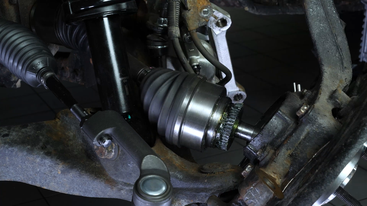
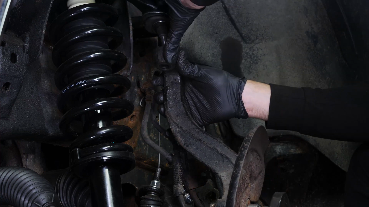
Chapter 10:
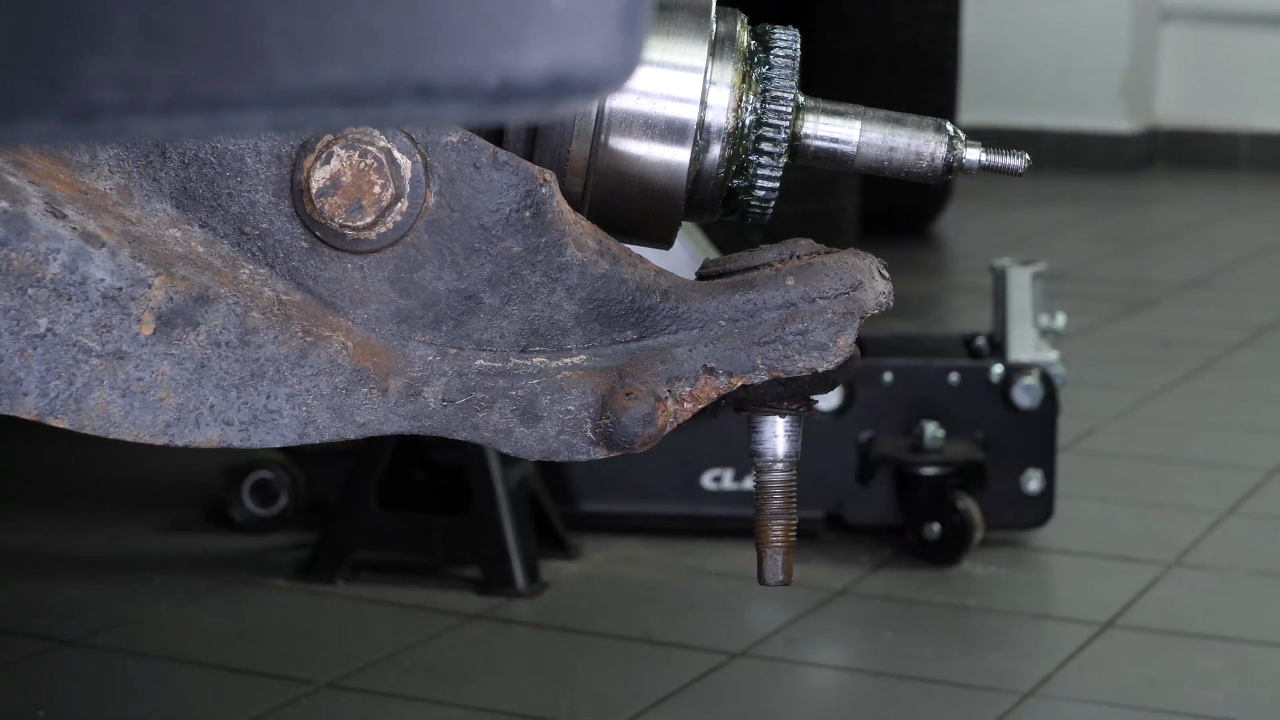
Step 4/4
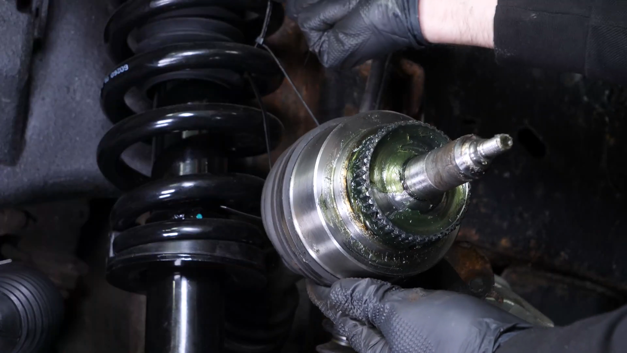
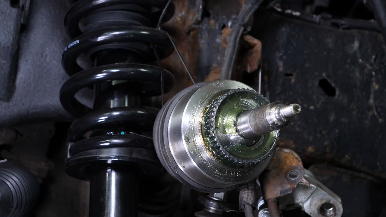
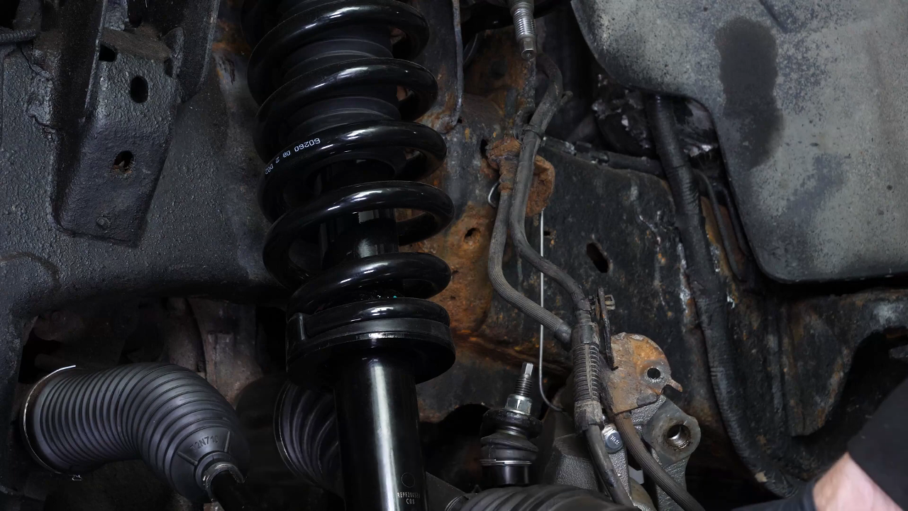
Attach the driveshaft to one of the strut spring coils to gain access to the strut foot screw.
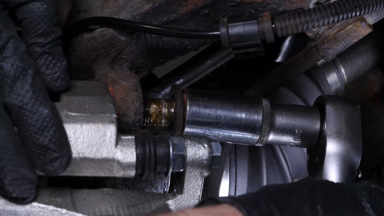
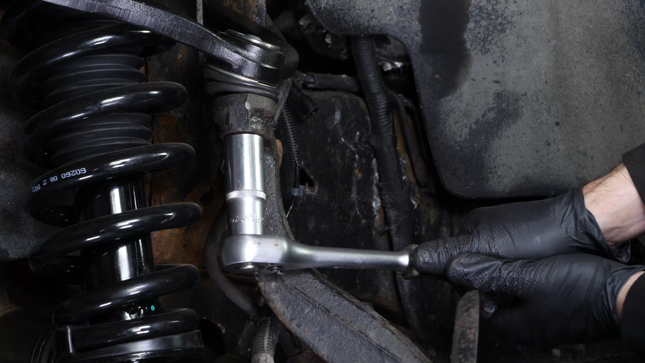
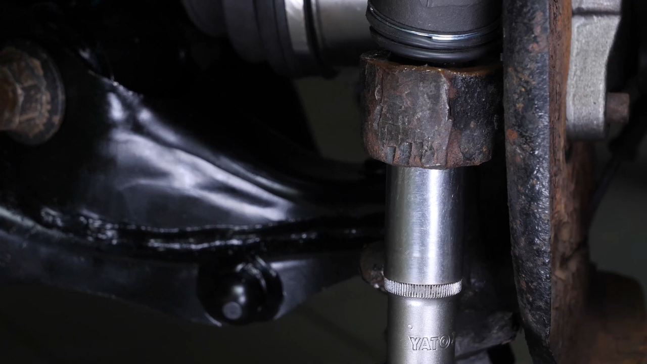
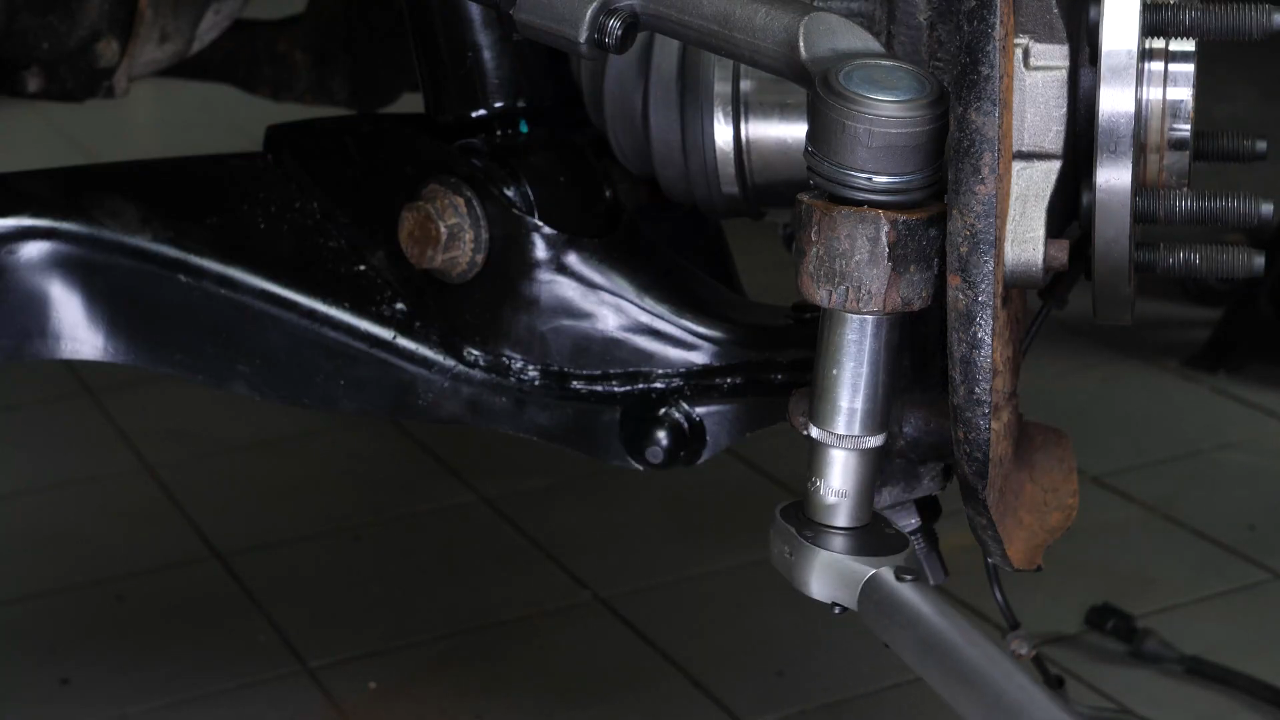
Chapter 11:
Remove the strut
Step 1/1
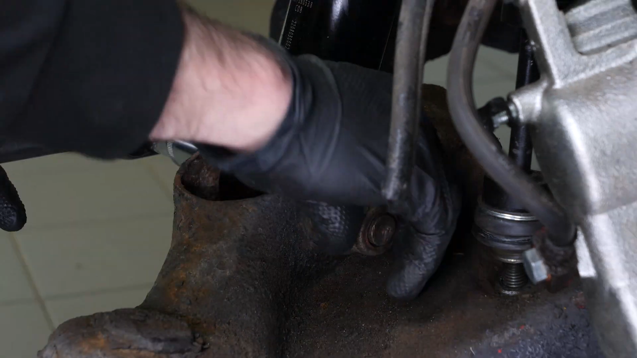
Then, using a breaker bar, a 30mm socket, a ratchet and 27mm socket, unscrew the strut foot nut, without extracting the screw.
Chapter 12:
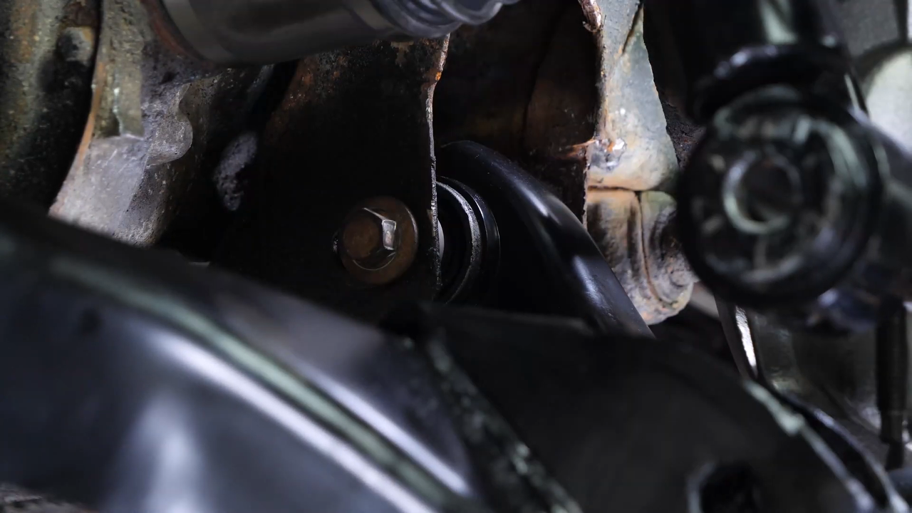
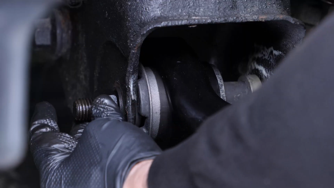
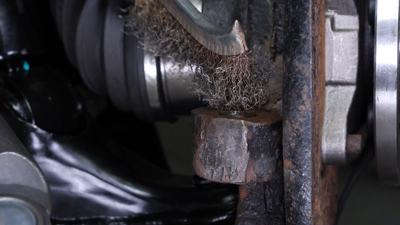
Rescrew the screws on the engine subframe side
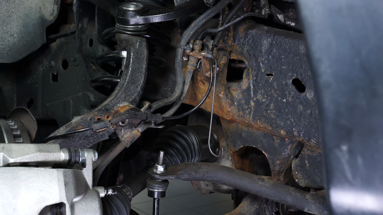
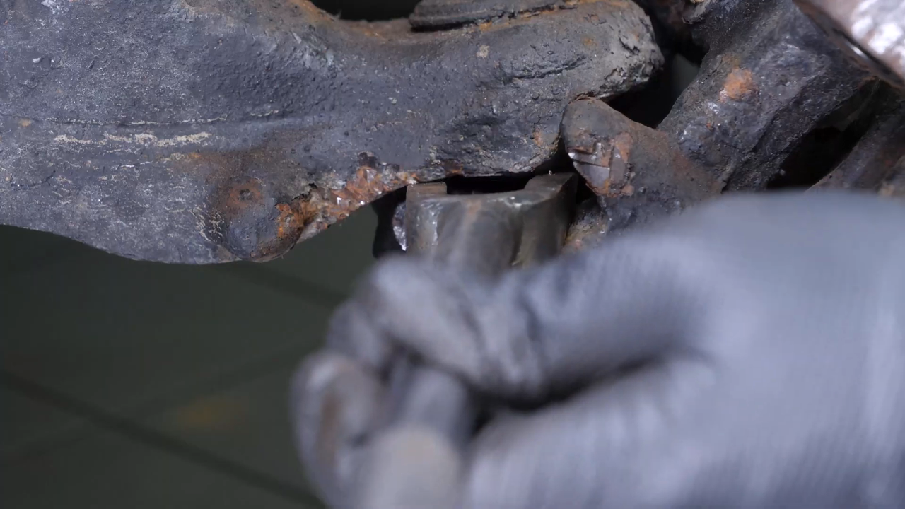
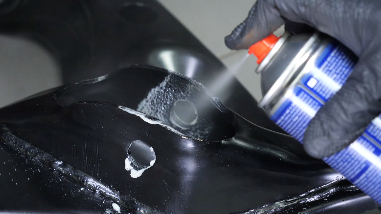
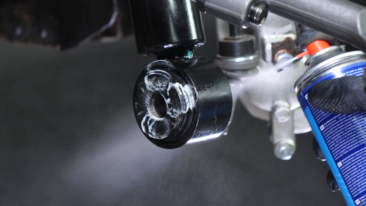
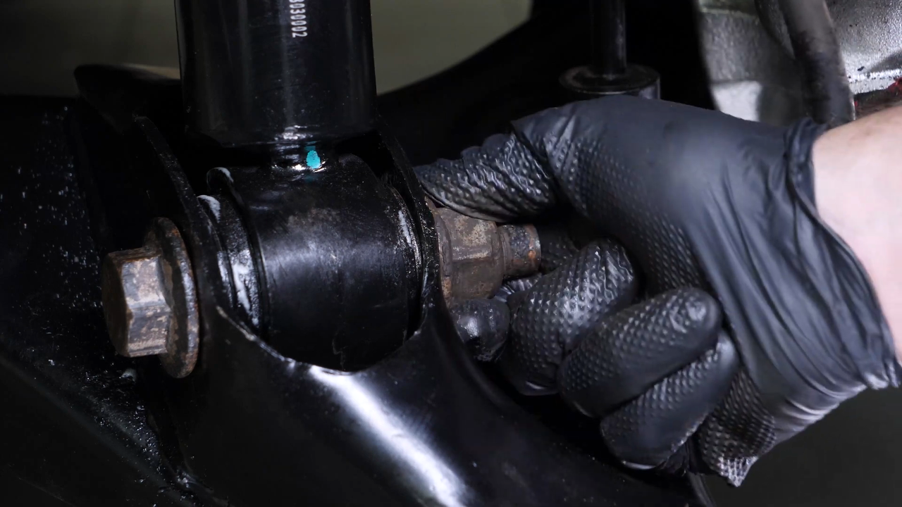
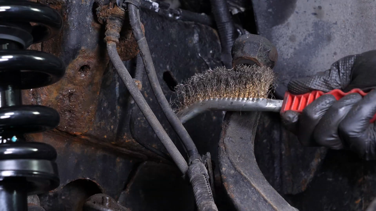
Step 1/3
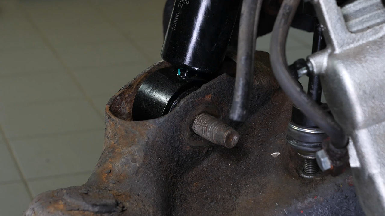
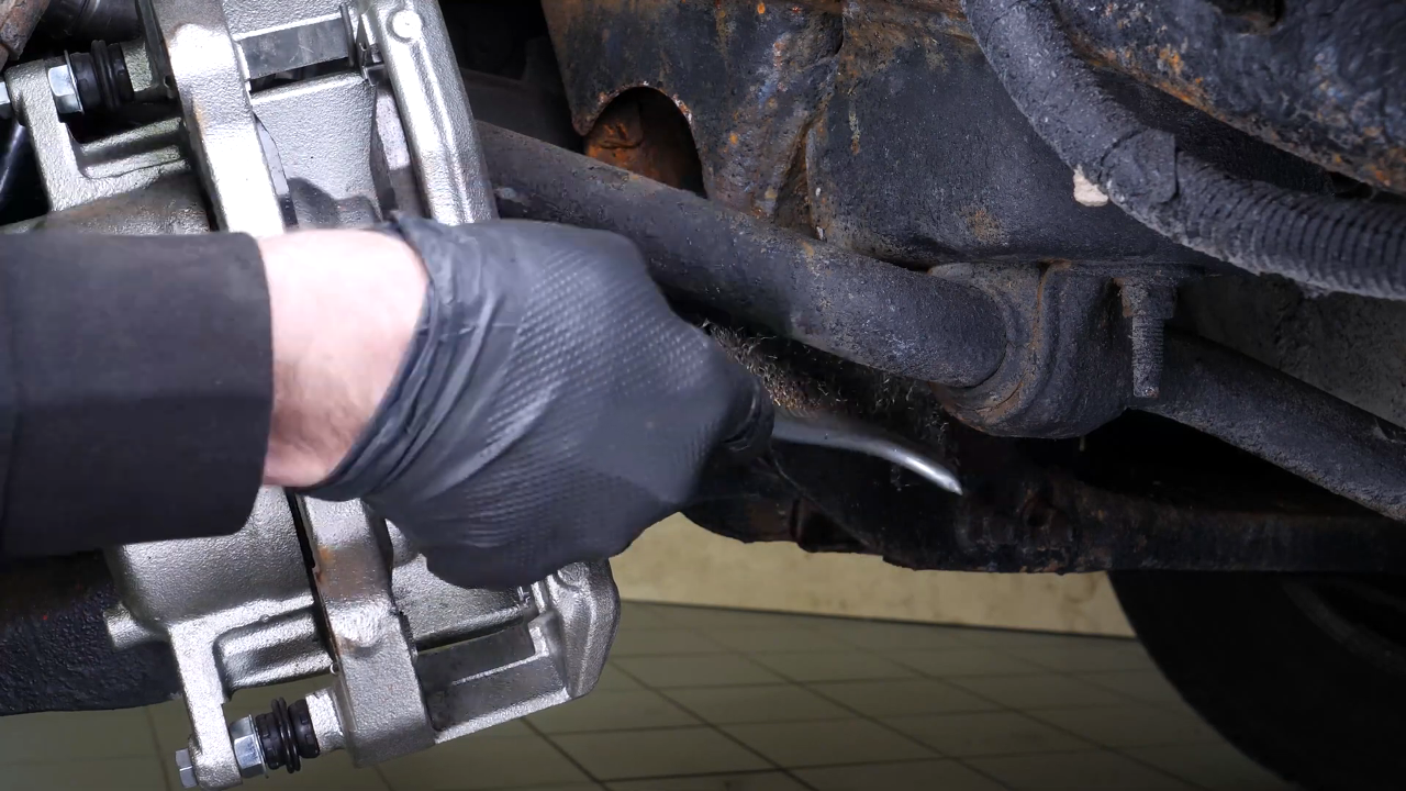
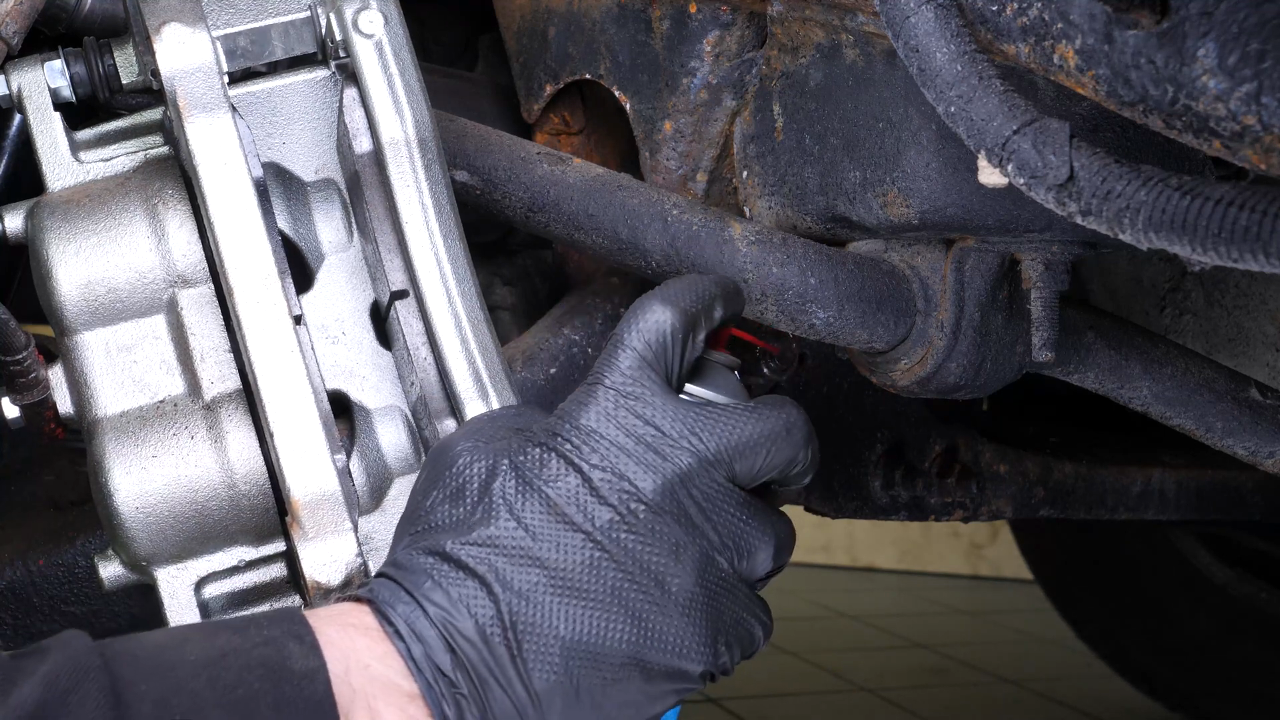
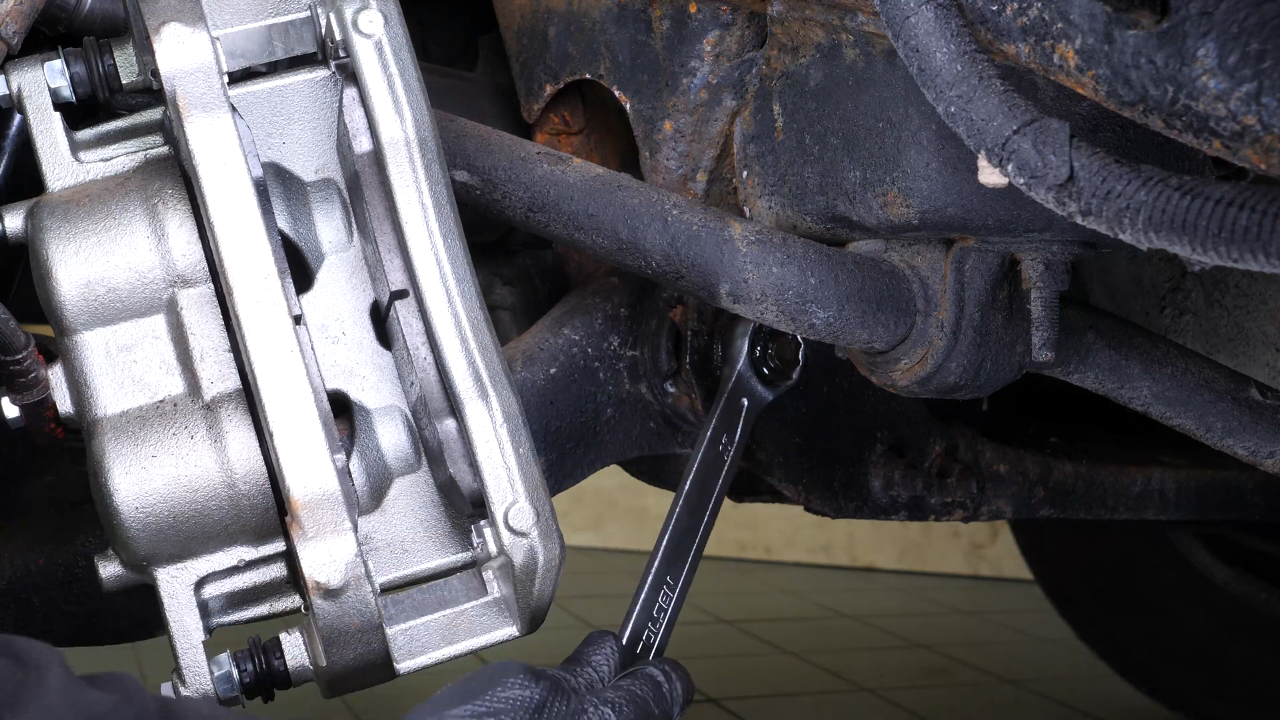
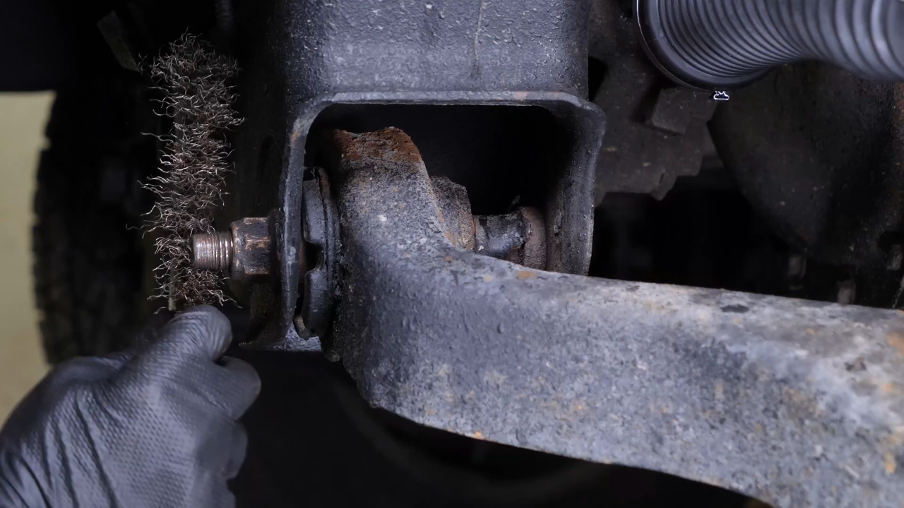
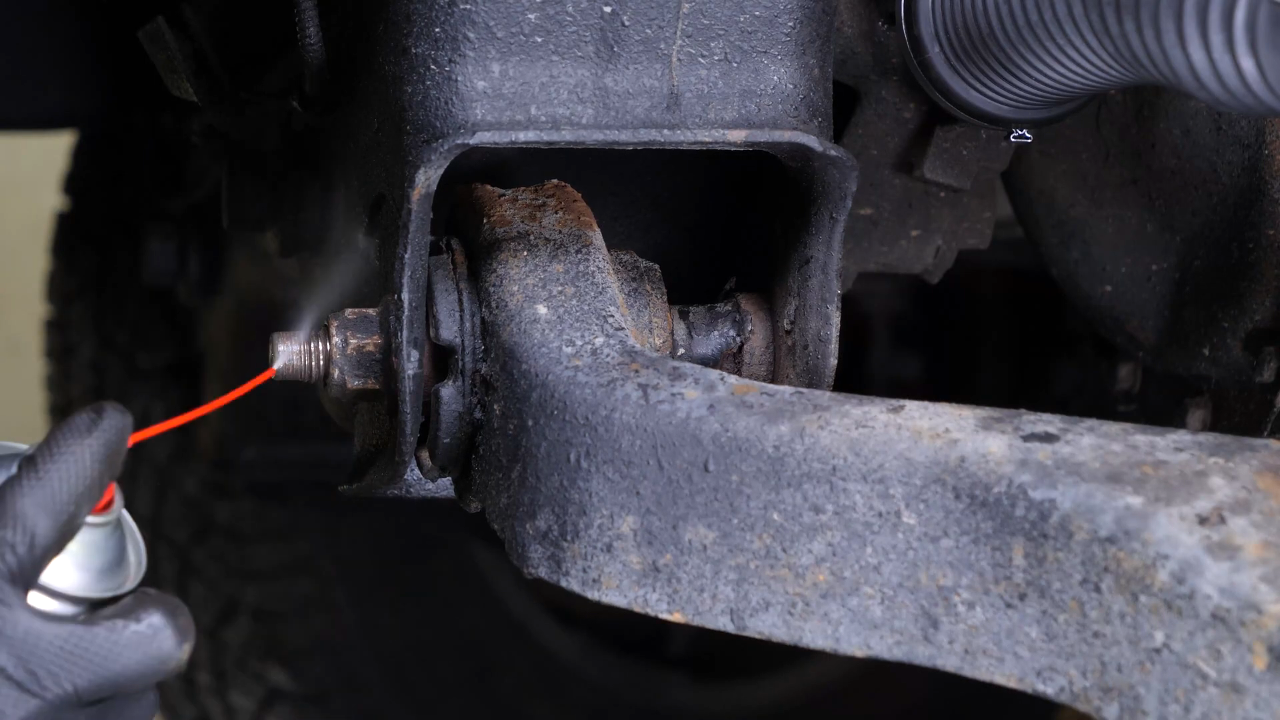
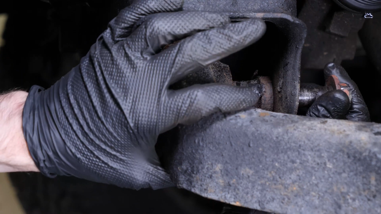
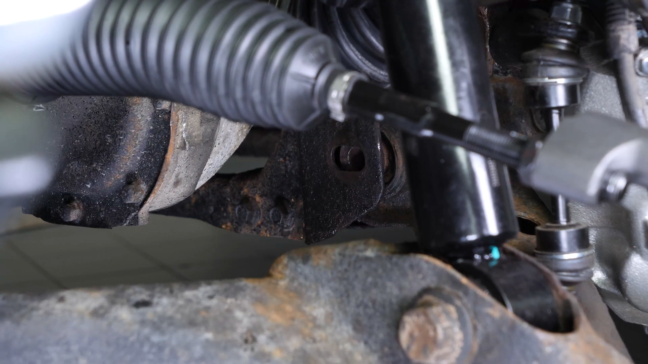
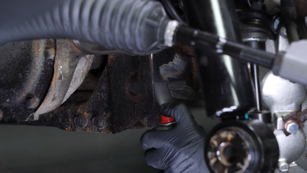
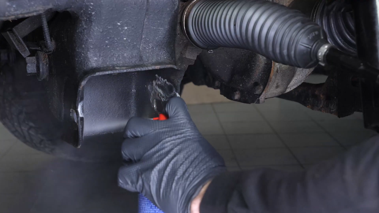
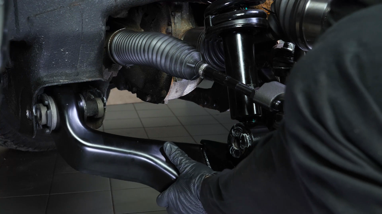
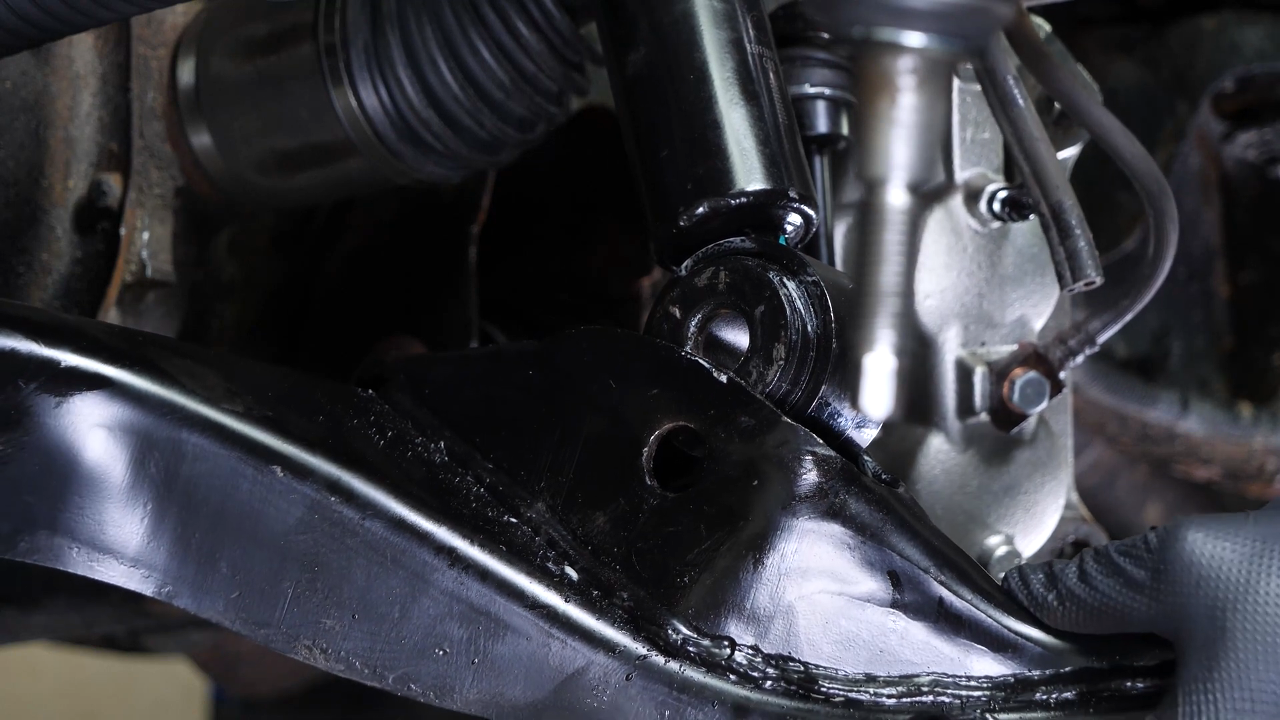
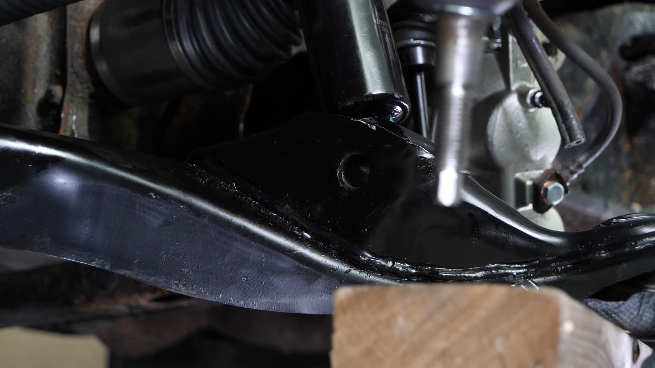
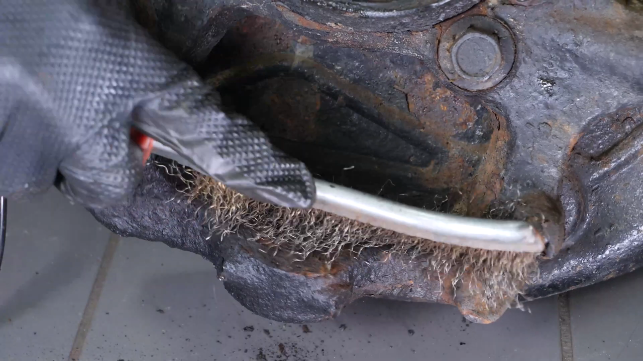
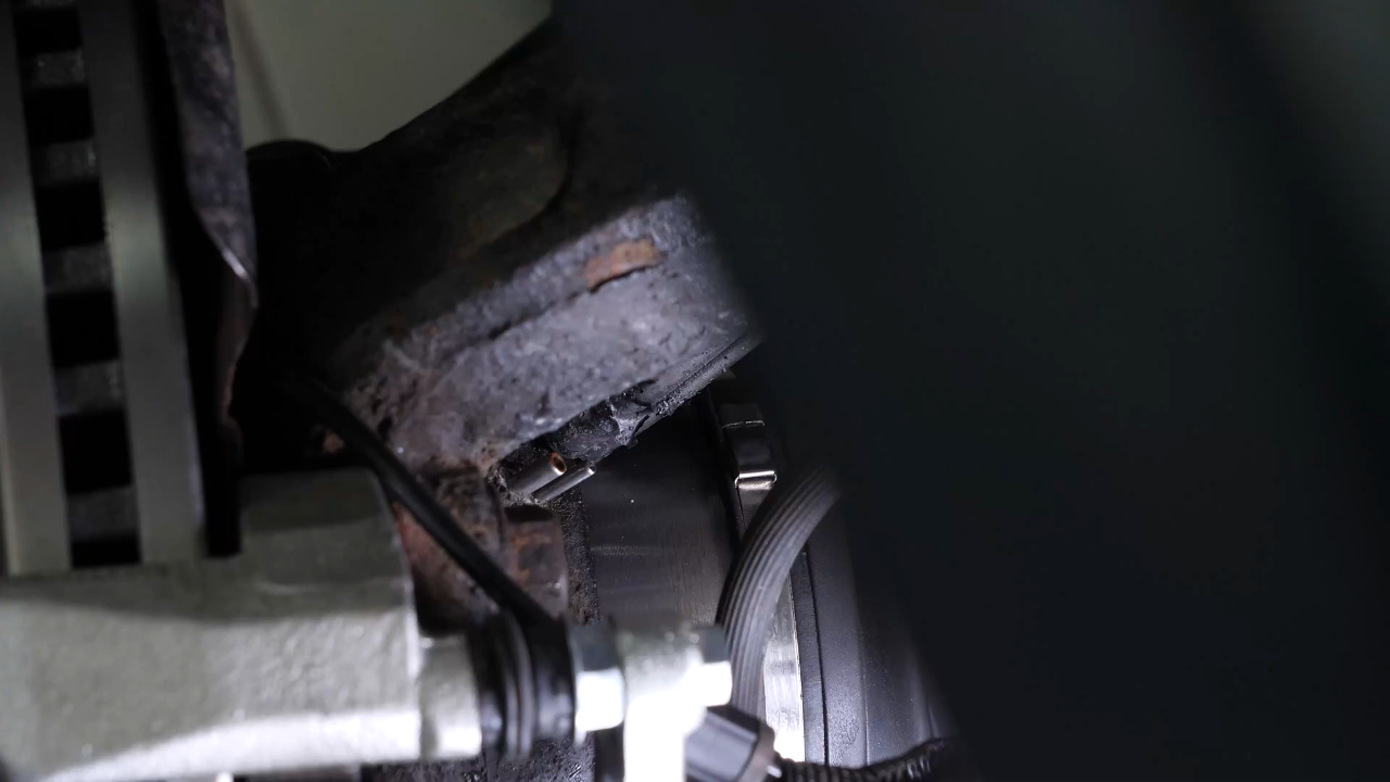
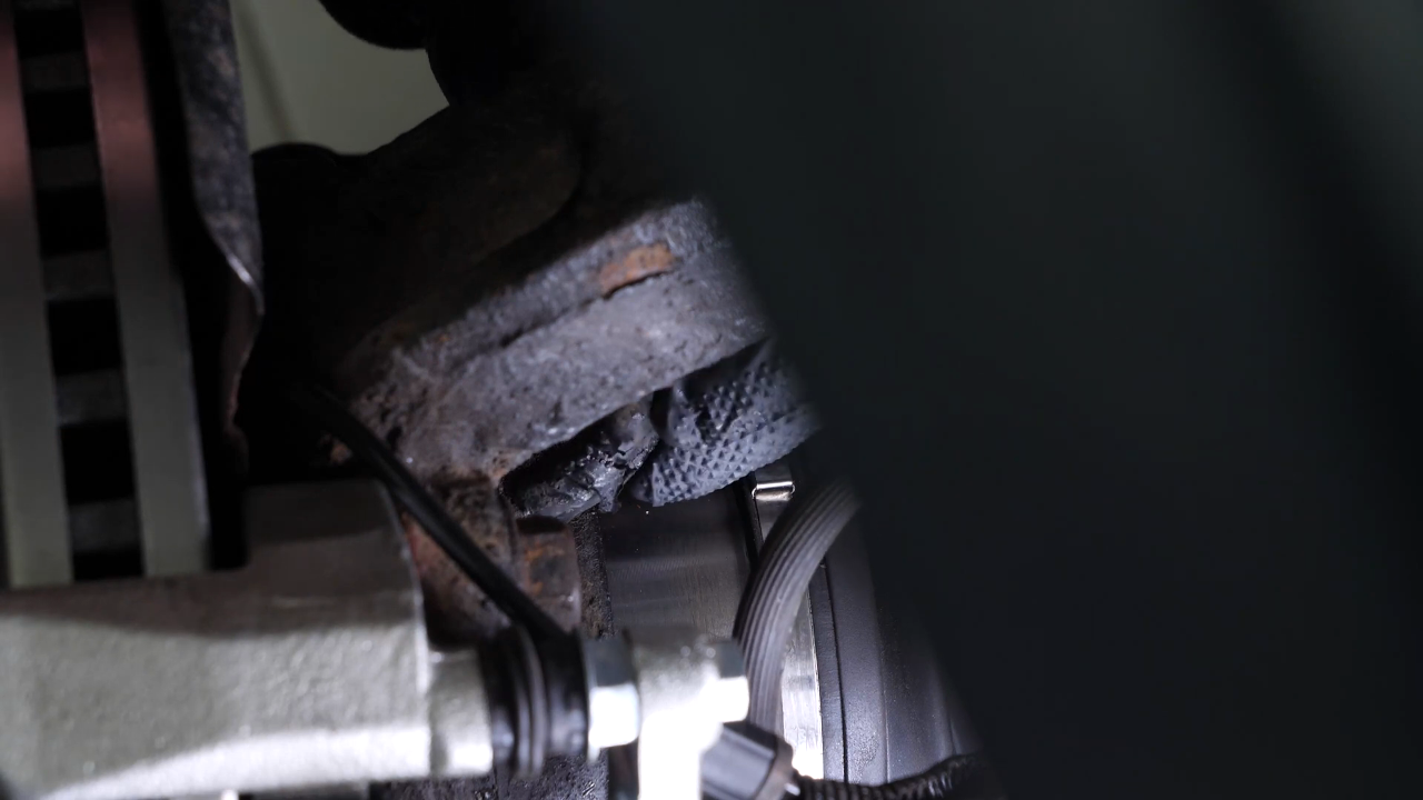
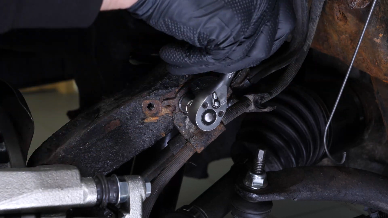
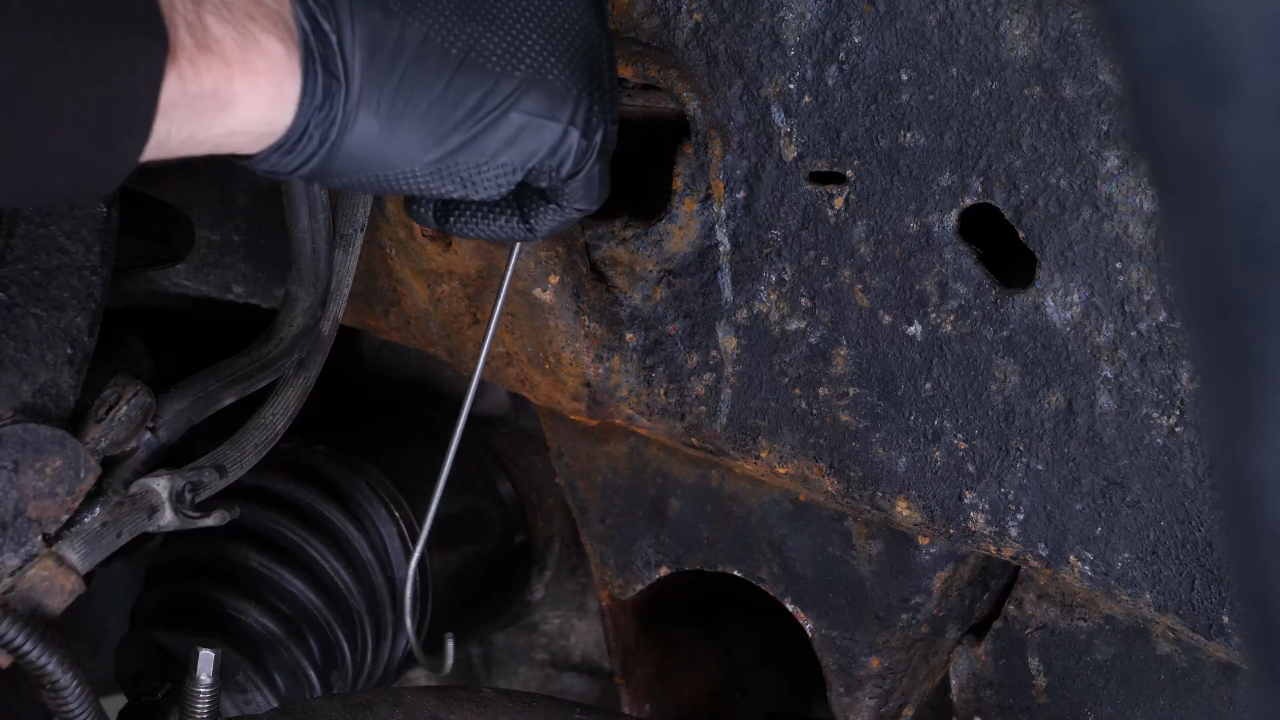
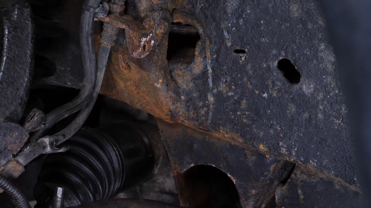
You now have access to the two silent block screws of the lower control arm. Brush the two nuts of the lower control arm silent block retaining bolts, and spray them with penetrating oil.
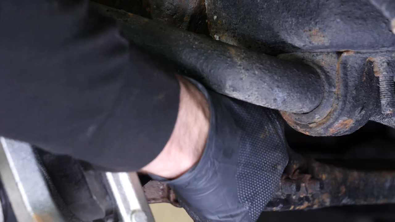
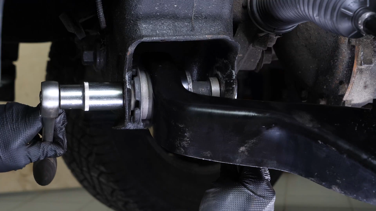
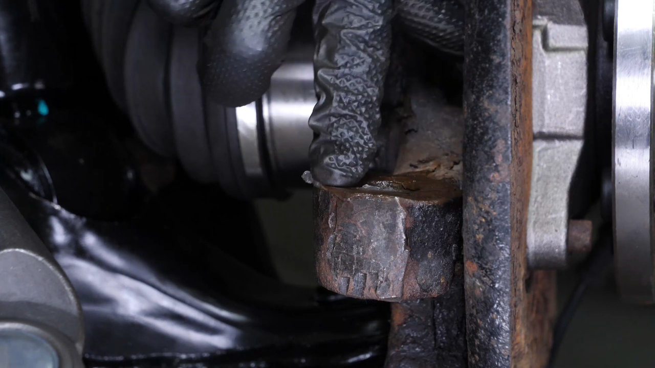
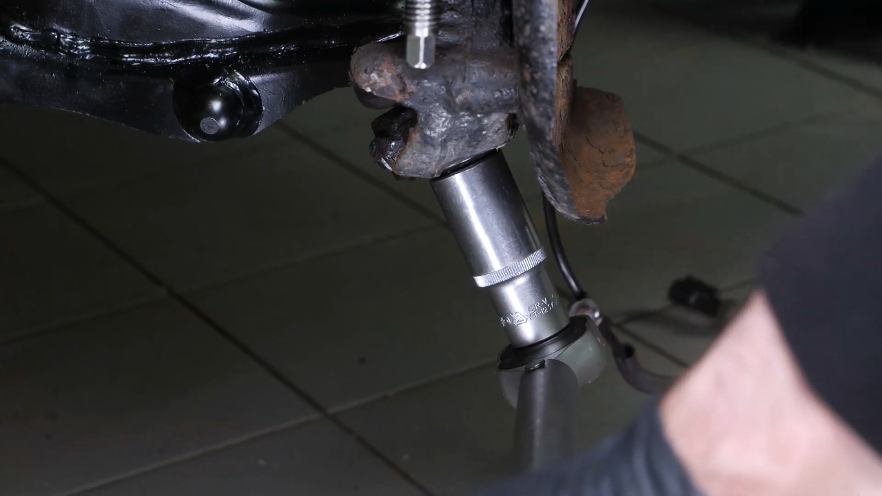
Chapter 12:
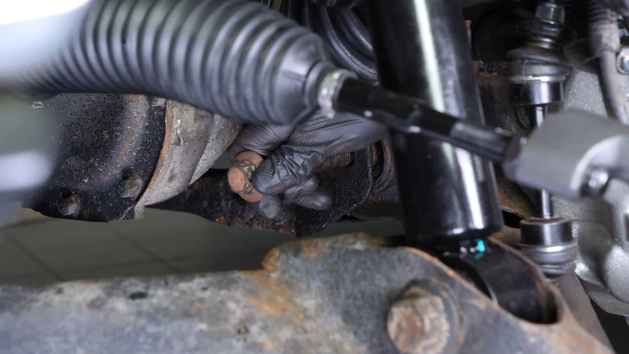
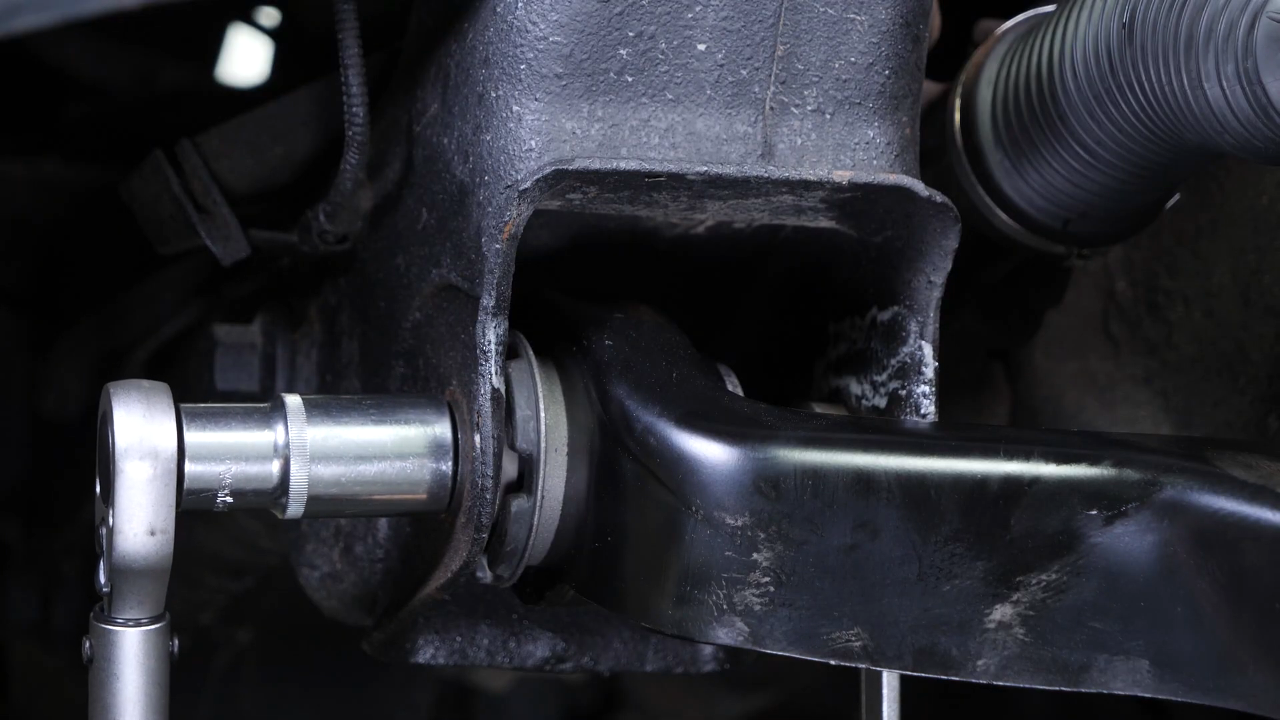
Step 2/3
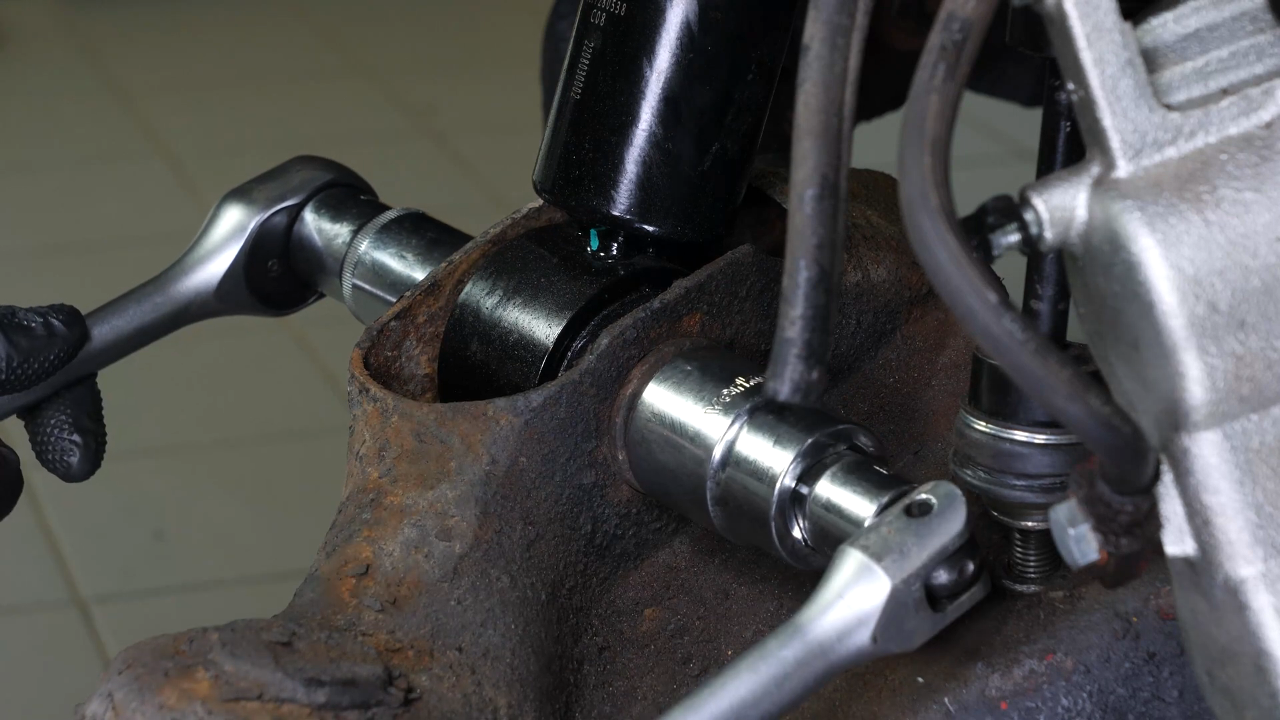
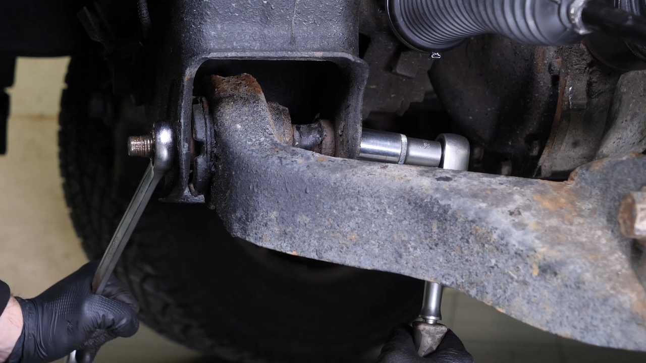
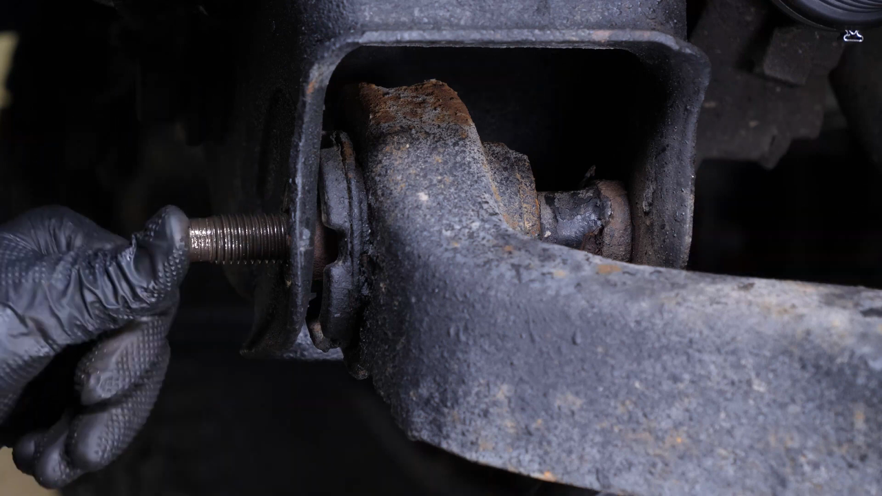
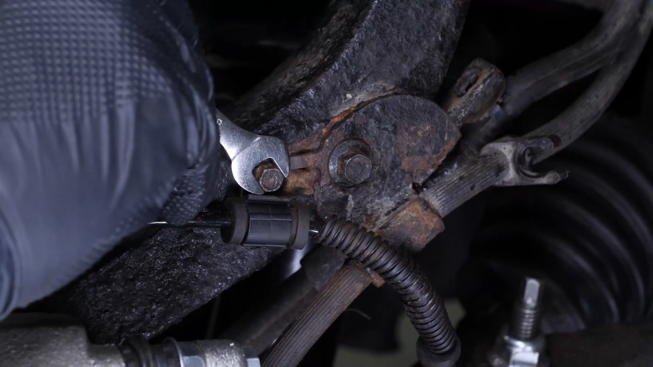
Using a 27mm spanner, lock the nut on the rear silent block retaining bolt, and unlock the bolt using a socket wrench and a 21mm socket.
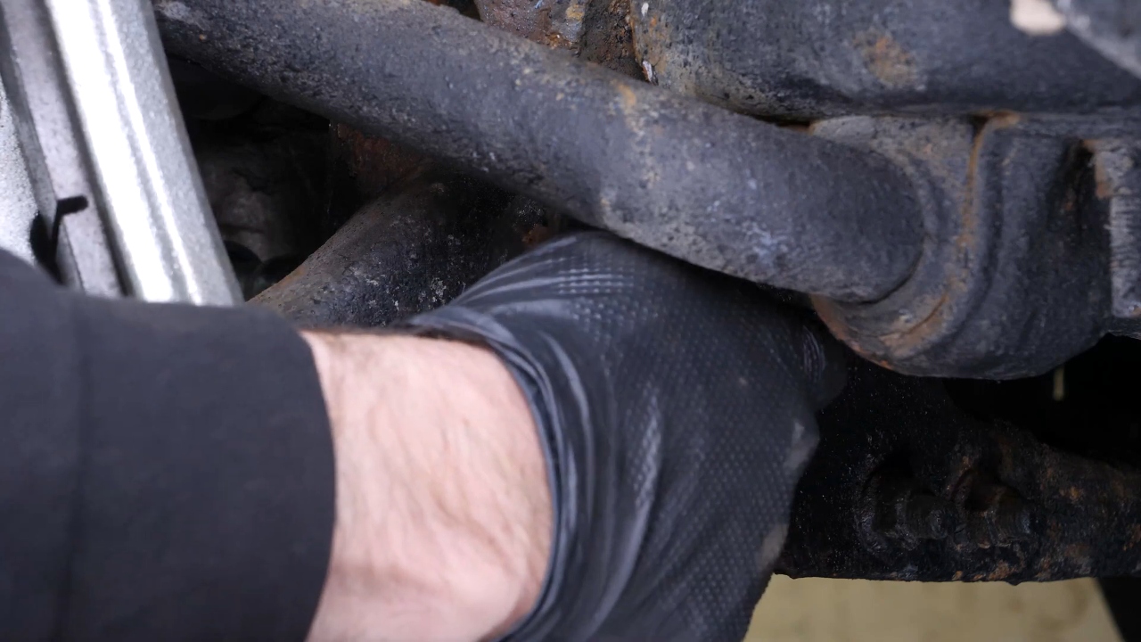
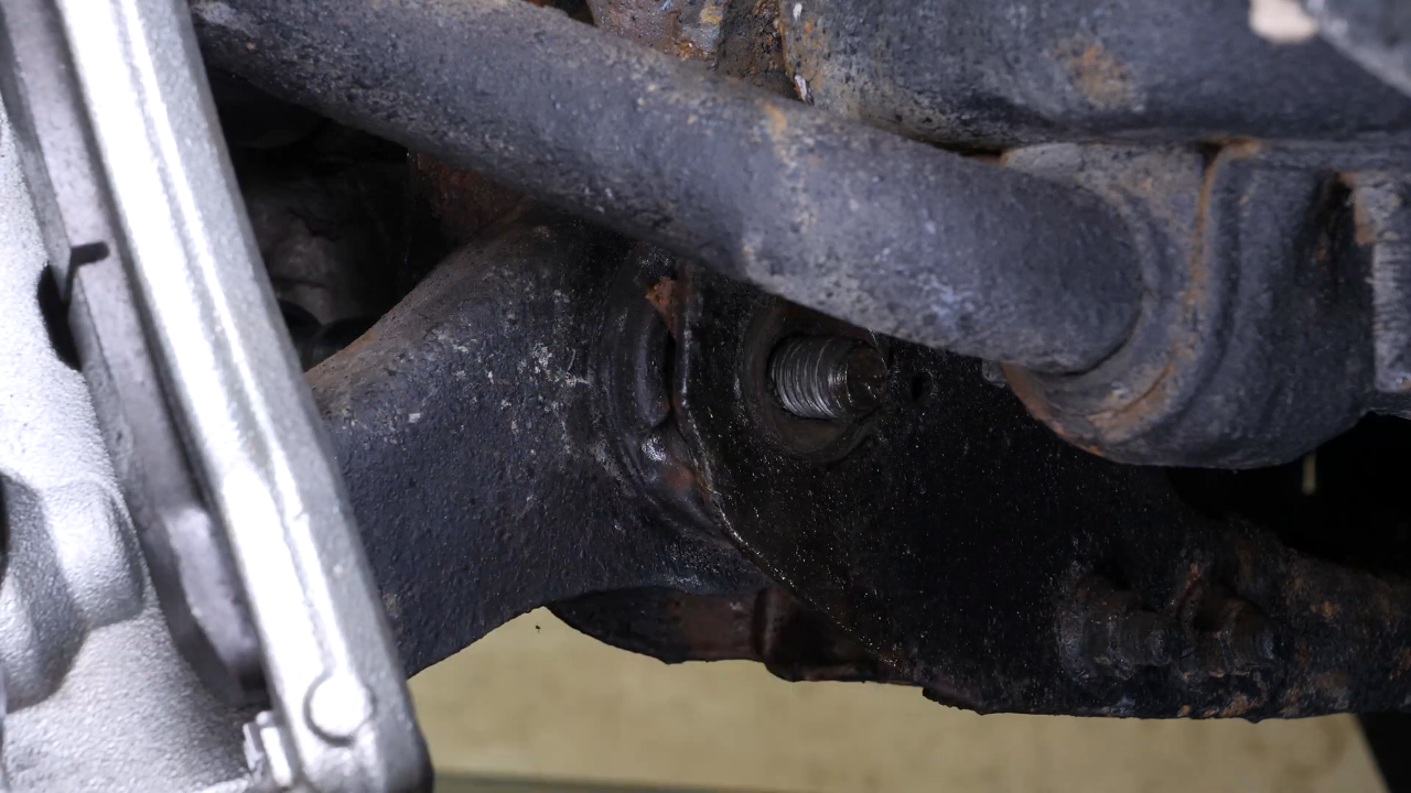

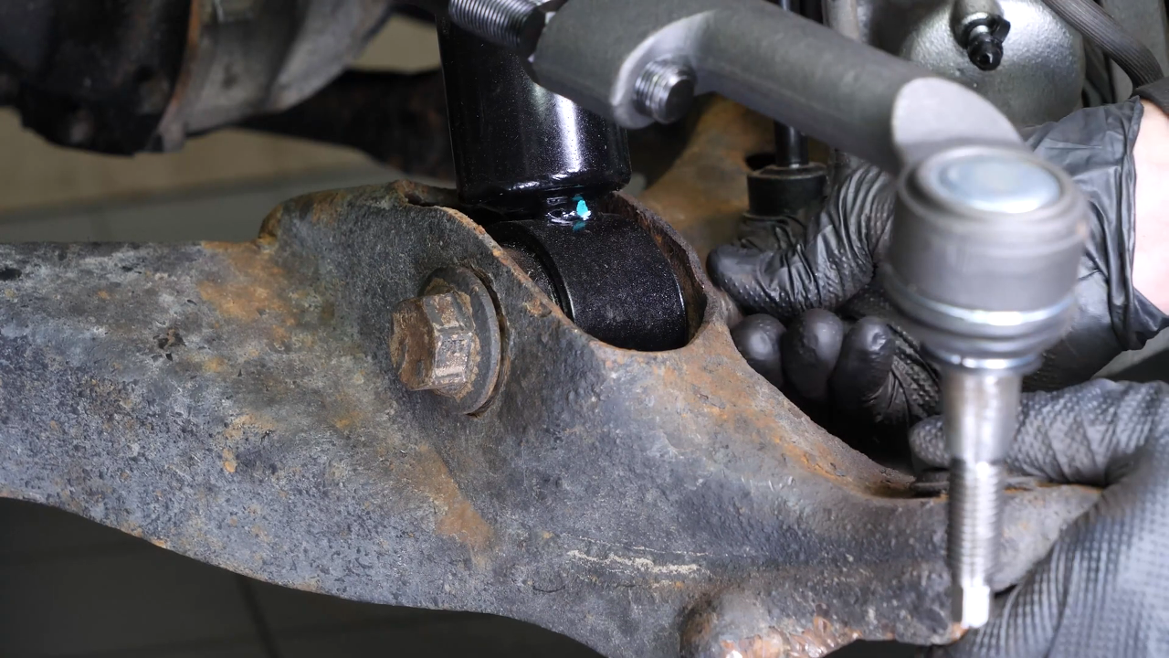
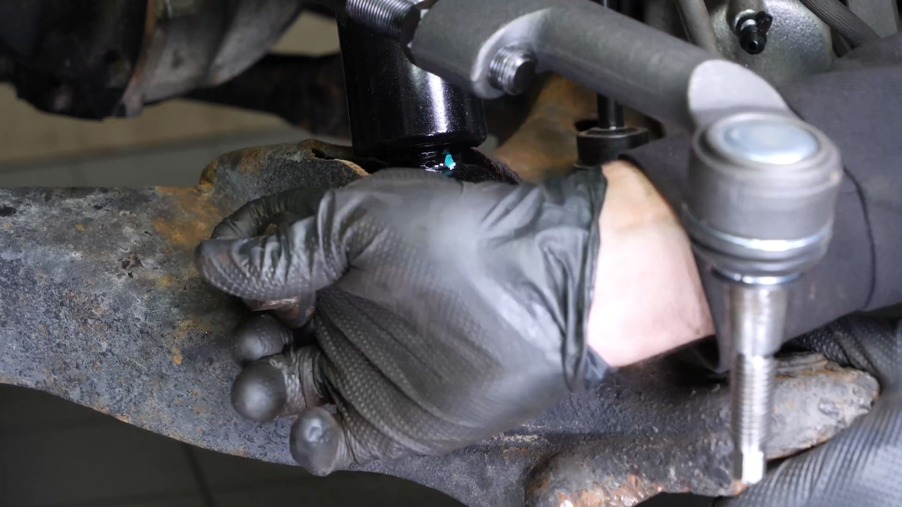
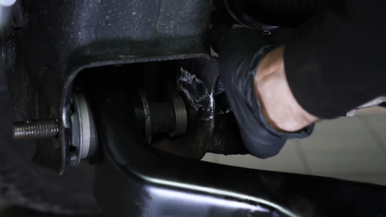
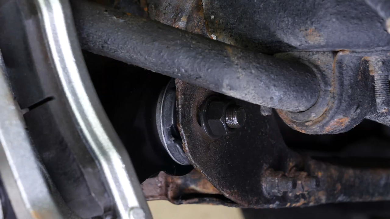
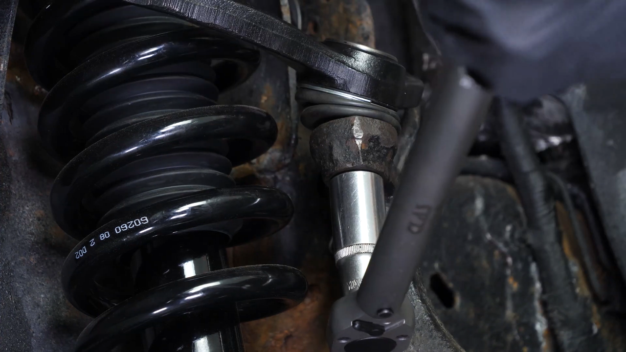
Chapter 12:
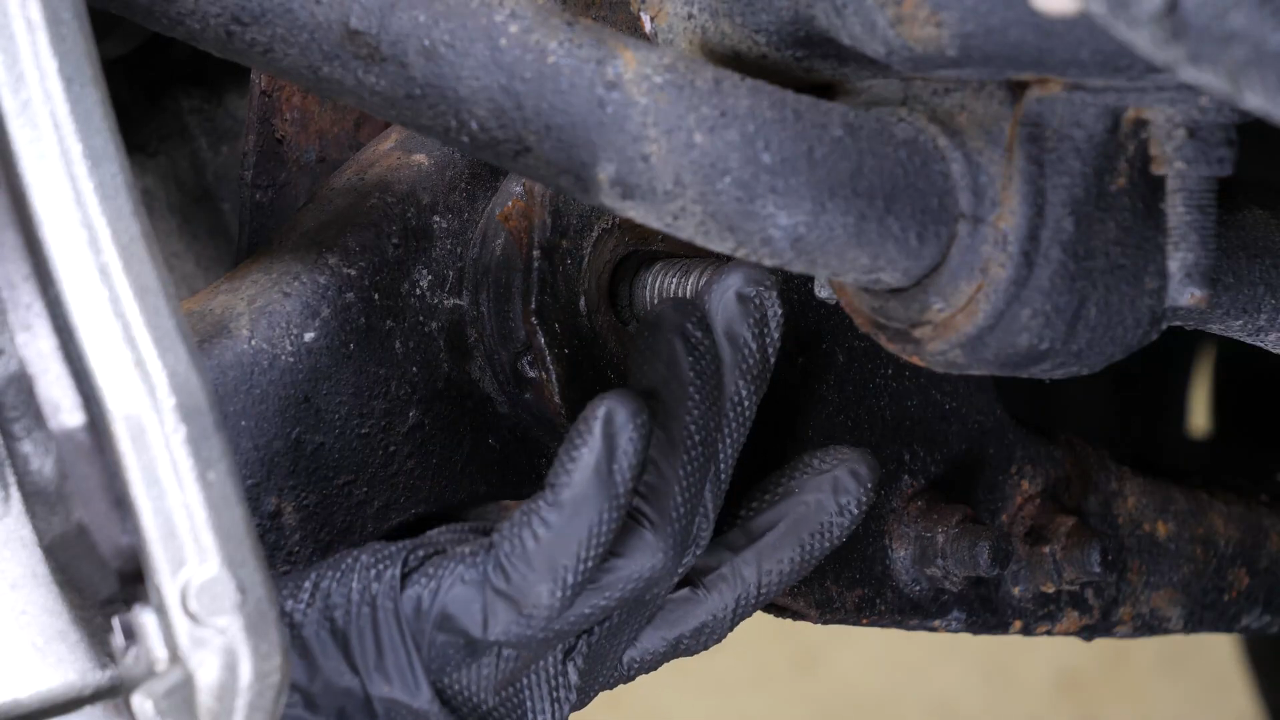
Step 3/3
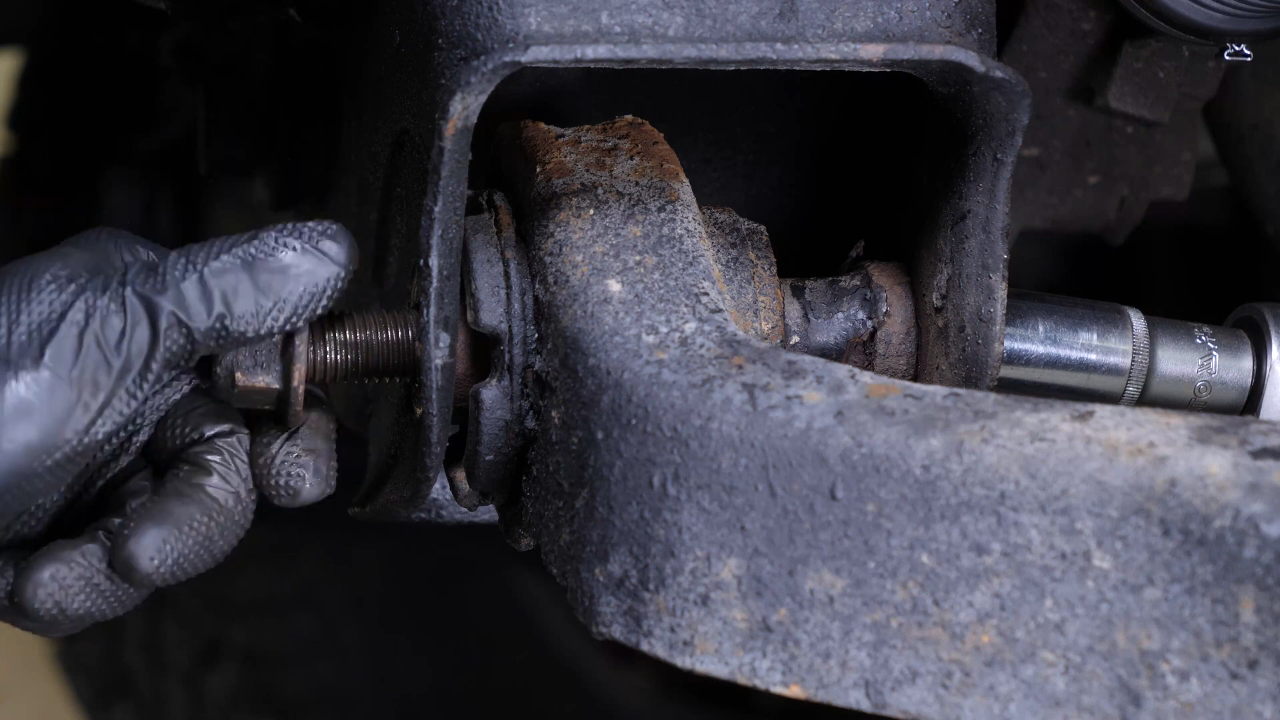
Using the same tools, repeat the operation on the front silent block screw. Then remove the screws. Extract the screw from the foot of the strut.

Chapter 13:
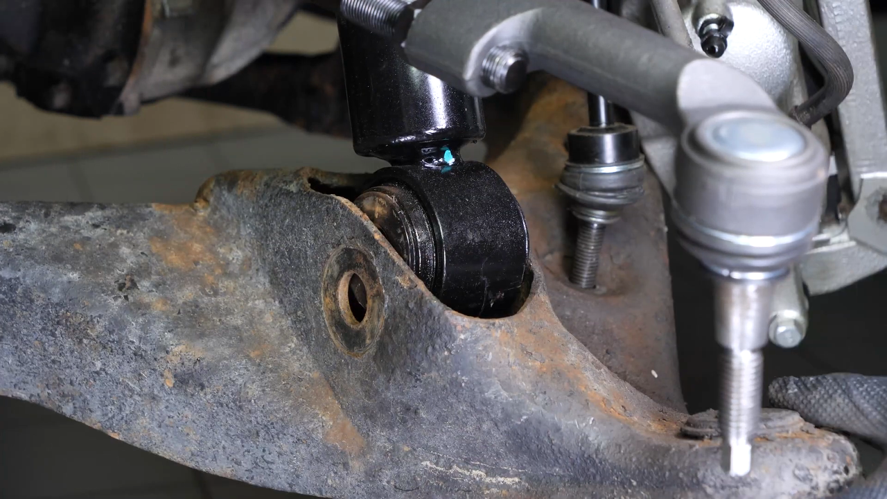
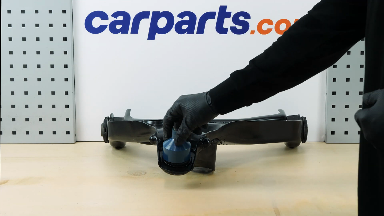
Remove the control arm
Step 1/1
You can now remove the lower control arm by pulling it towards you and moving it back and forth.
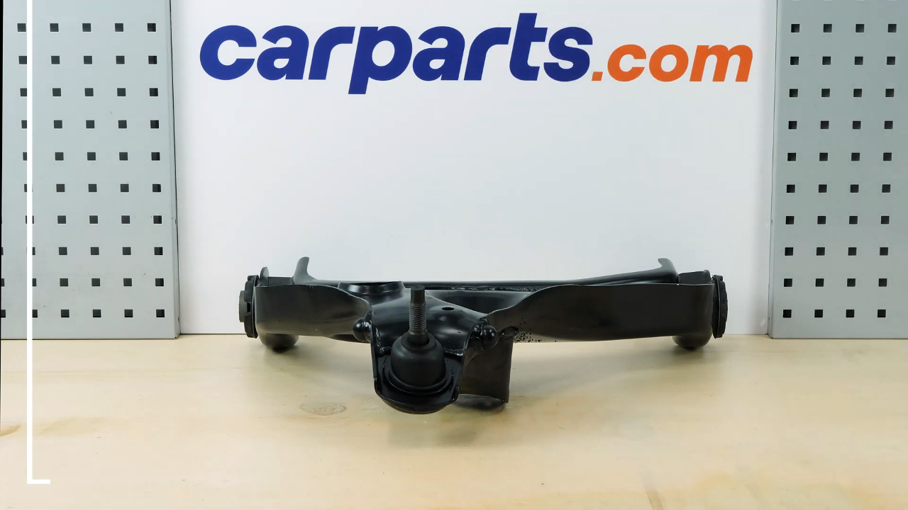
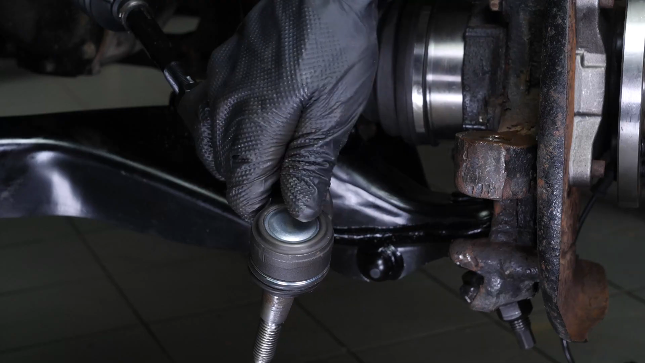
Chapter 14:
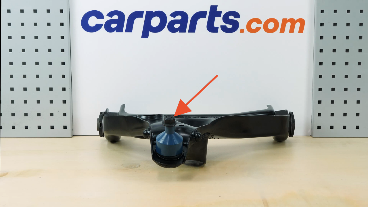
Prepare the new control arm
Step 1/3
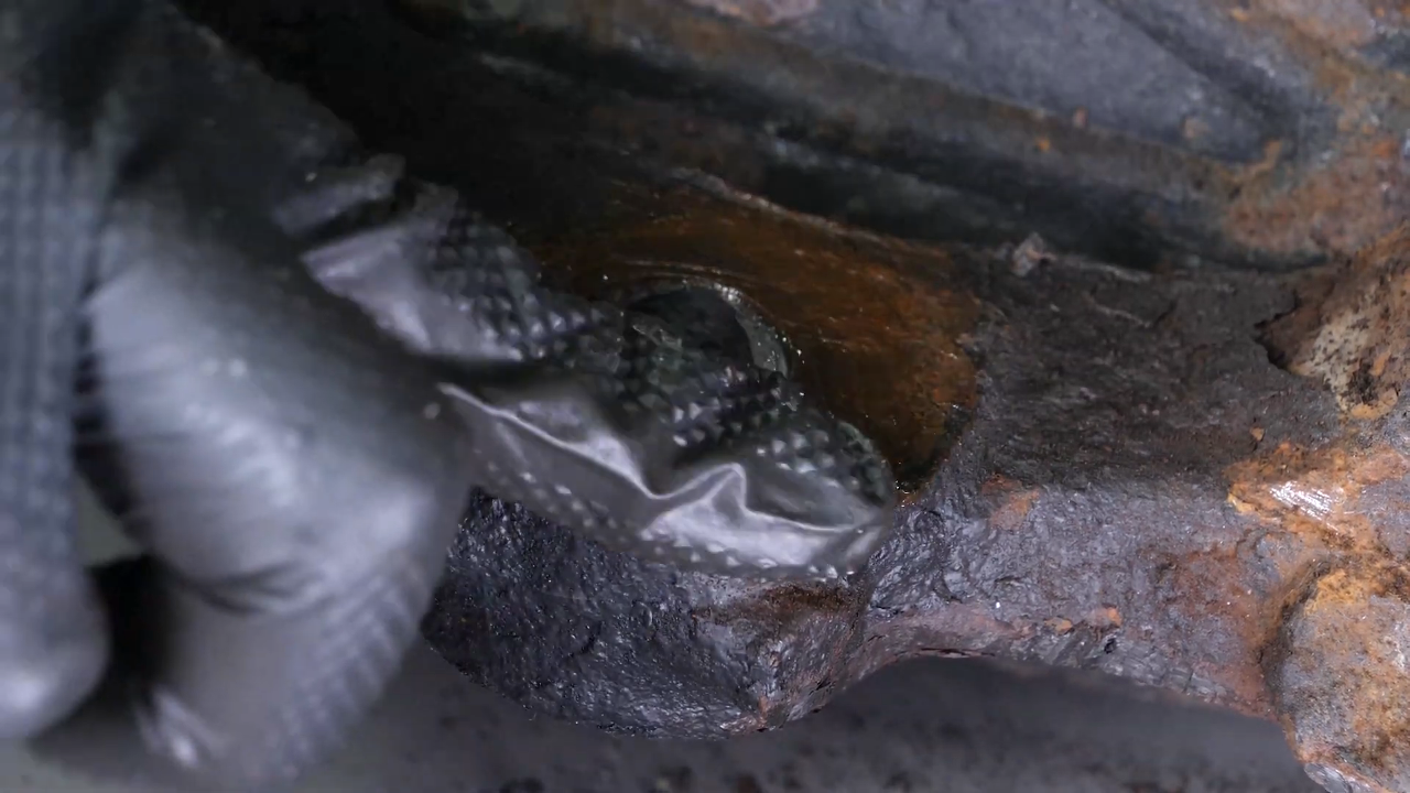
Brush and grease the control arm area to facilitate its installation.
Chapter 14:
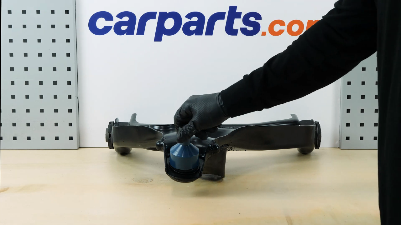
Step 2/3
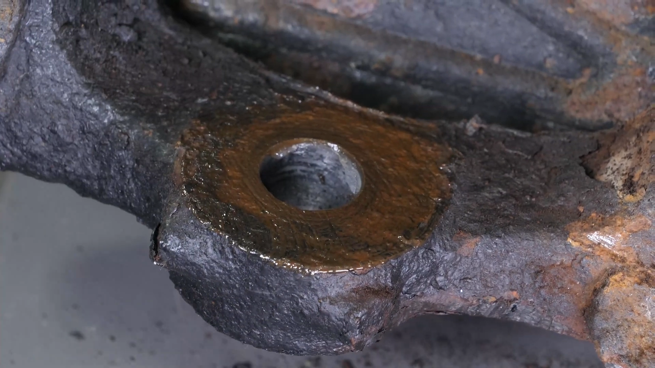
Unscrew the ball joint retaining screw. Take the control arm. Grease the location of the strut foot and its silent block.
Chapter 14:
Step 3/3
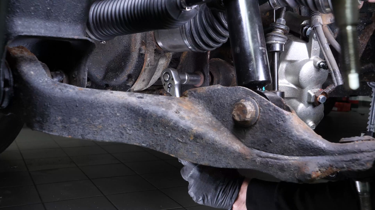
Then install the control arm. Replace the screws on the cradle side.

Chapter 15:
Install the new strut
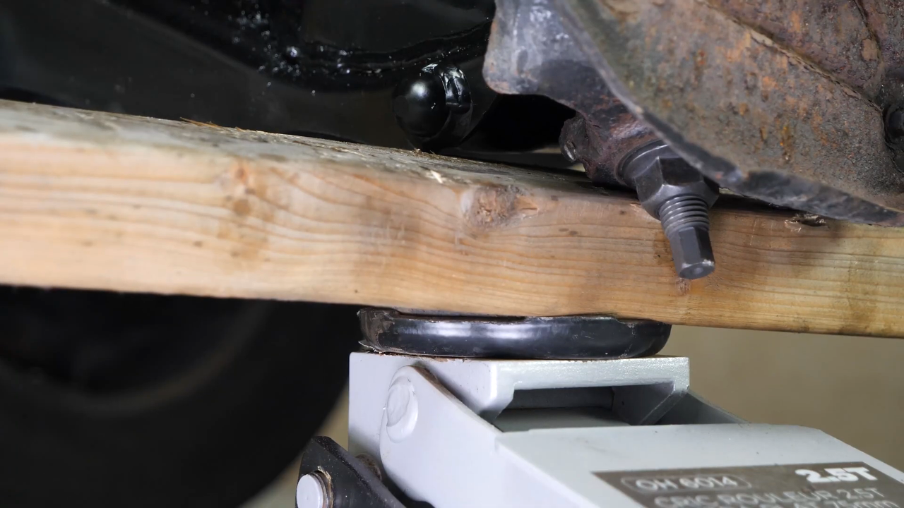
Step 1/3
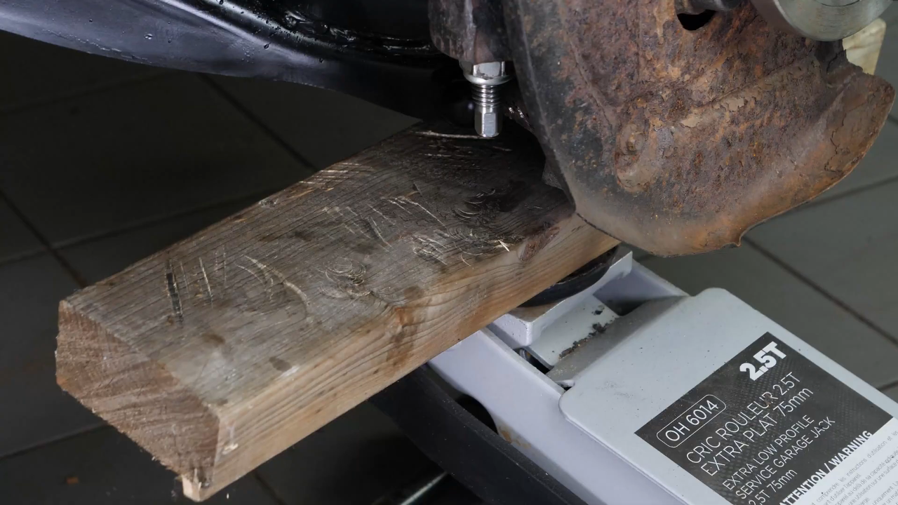
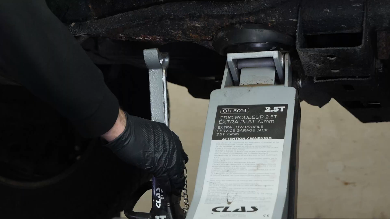
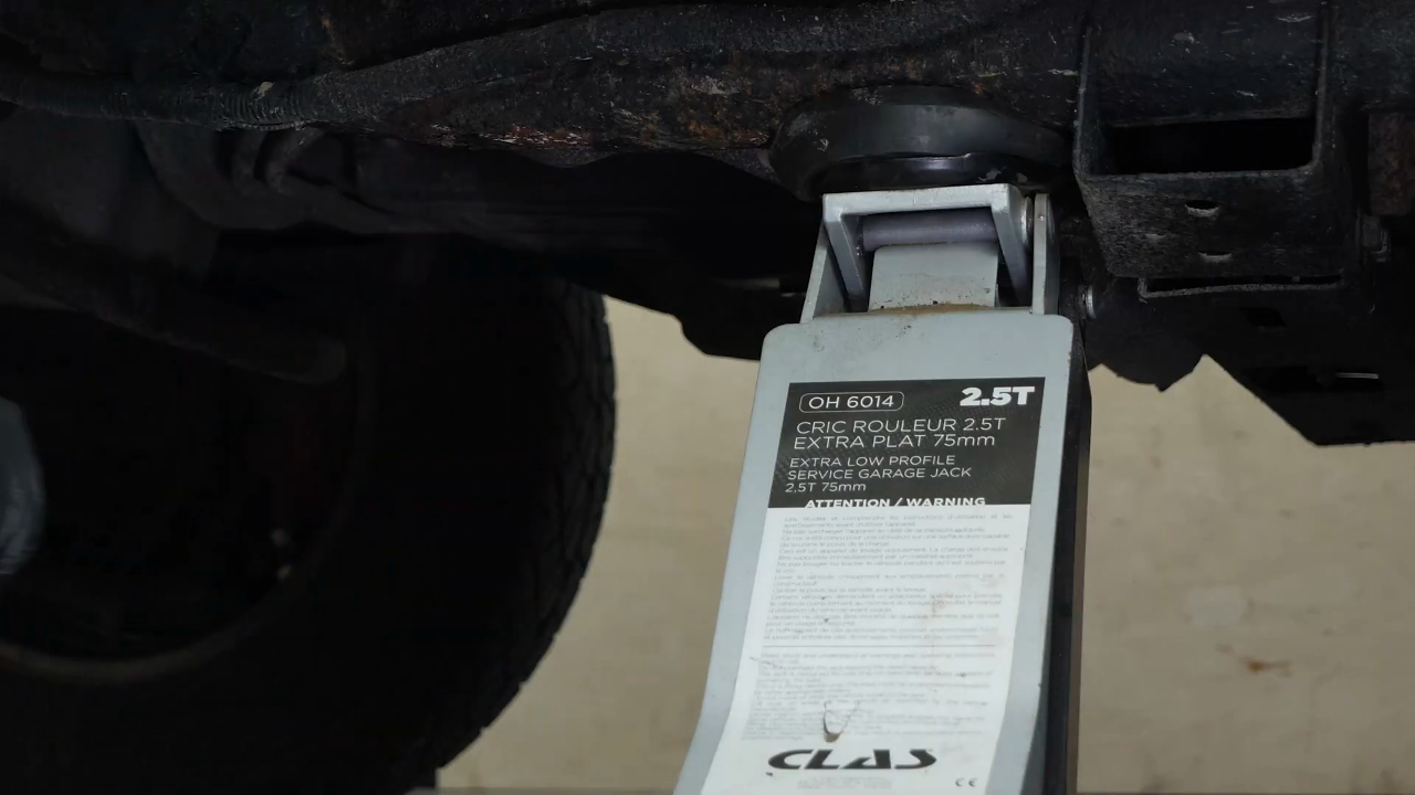
It is then necessary to insert the strut foot into the control arm. To do this, we advise you to use a jack to apply pressure to the control arm.
Chapter 15:
Step 2/3
Then insert the screws back in. You can use a hammer to help you. Screw the nut back on until it makes contact. Roughly refit the nuts of the control arm silent blocks.

Chapter 15:
Step 3/3
Using a wire brush, scrub the knuckle of the wheel knuckle, then apply silicone grease to the flat part that will be in contact with the lower control arm ball joint sleeve.
Chapter 16:
Screw the control arm ball joint nut back
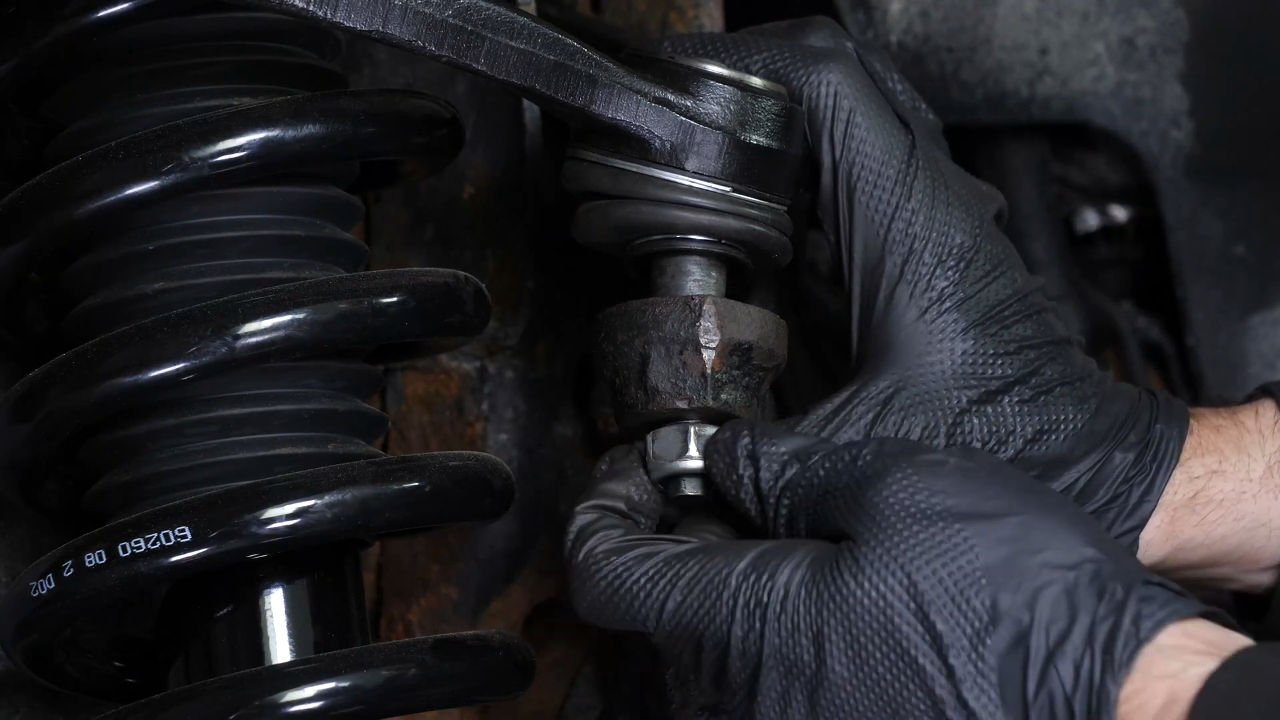
Step 1/4
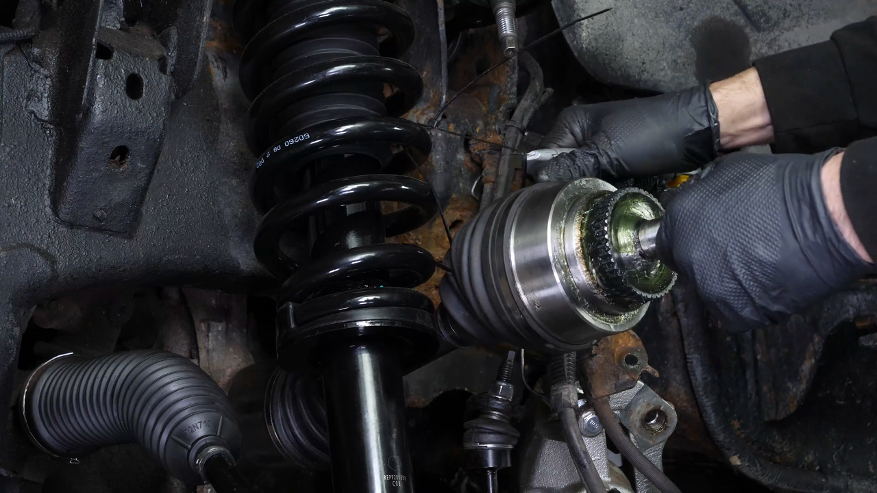
Detach the driveshaft. Take the wheel knuckle and, while inserting the control arm ball into its knuckle, thread the driveshaft into the hub. Secure the whole by screwing the nut on the ball joint a few threads by hand.
Chapter 16:
Step 2/4
Once in place, tighten the nut to the point of contact using a 24mm spanner, ratchet and 12mm socket to lock the rotation of the ball joint.
Chapter 16:
Step 3/4
Using a wire brush, scrub the knuckle of the wheel knuckle, then apply silicone grease to the flat part that will be in contact with the lower control arm ball joint sleeve. Do not grease the inside of the cone.
Chapter 16:
Step 4/4
Then insert the upper control arm into the wheel knuckle. Then screw the nut back on by hand a few threads.
Chapter 17:
Put the outer tie rod back
Step 1/5
Insert the drive shaft into the hub properly. Using a wire brush, scrub the knuckle of the wheel knuckle, then apply silicone grease to the flat part that will be in contact with the sleeve of the outer tie rod.
Chapter 17:
Step 2/5
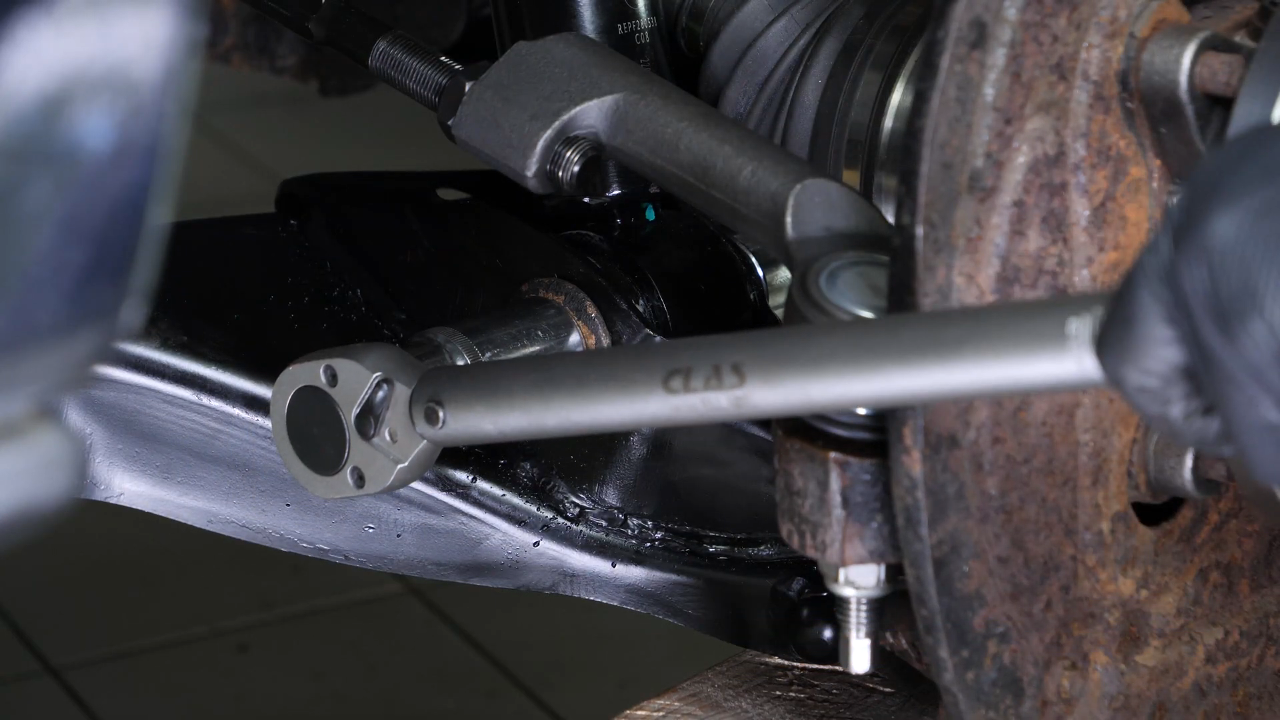
Put the outer tie rod back in place. Then screw it back on. Finish tightening using a torque wrench.


Chapter 17:
Step 3/5
You can now complete the tightening of the upper control arm ball joint. Finish tightening using a torque wrench.
Chapter 17:
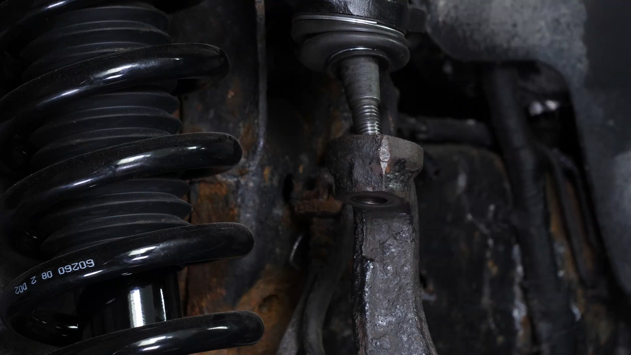
Step 4/5
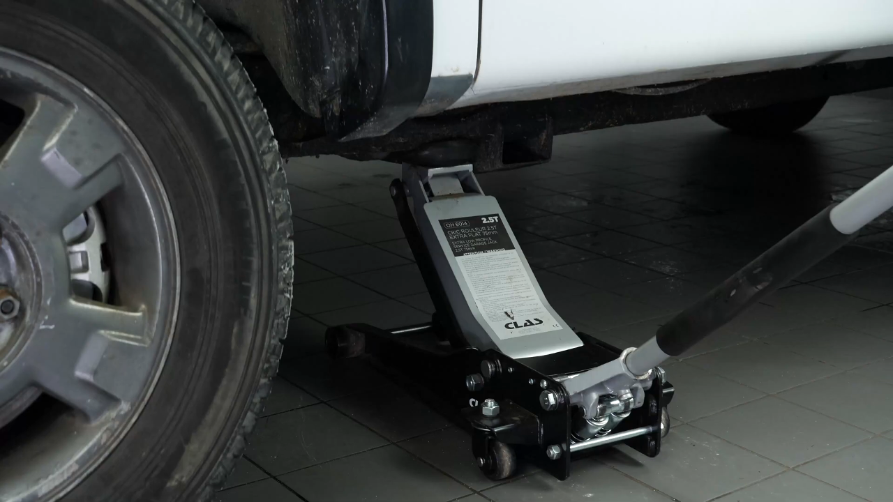
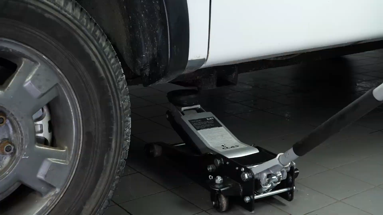
You can now complete the tightening of the lower control arm ball joint with a torque wrench. It is necessary to tighten the front retaining bolts in the “vehicle on the ground” position. Lift the wheel knuckle unit with the jack until the original measurement between the center of the wheel and the wheel arch is reached. Complete then the tightening of the silent blocks holding screws. Finish tightening using a torque wrench.
Chapter 17:
Step 5/5
Do the same with the strut foot screw. Remove the jack.
Chapter 18:
Put the components back in place
Step 1/4
You can now put the sway bar end link back in place, and screw it back in. Finish tightening using a torque wrench.
Chapter 18:
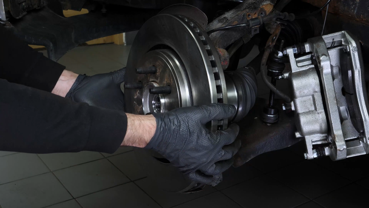
Step 2/4
Reinstall the brake disc. You can now re-install the caliper assembly. And screw it back on. Finish tightening using a torque wrench.

Chapter 18:
Step 3/4
Reconnect the vacuum lines. Screw the brake hose mounting bracket back on. Don’t forget to remove the cable that you used to hold the caliper assembly together. Replace the ABS sensor cable and clip it back into its slots. Then reconnect it.
Chapter 18:
Step 4/4
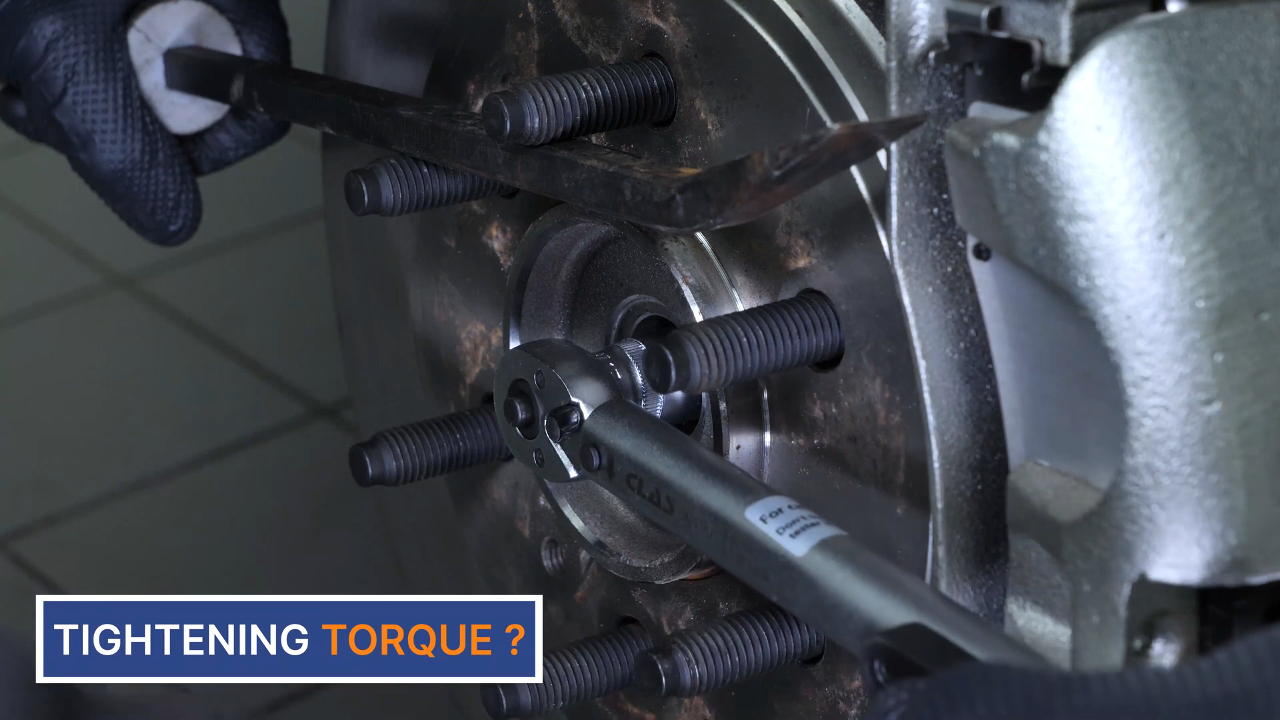
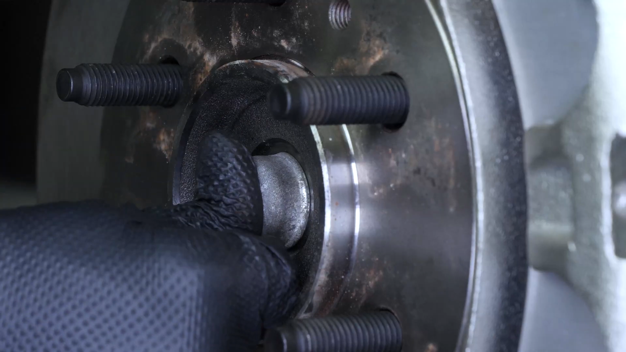
Replace the hub nut. Then, while blocking the rotation of the hub with a crowbar, screw it back on. Finish tightening using a torque wrench. Put the cover back on the nut.
Chapter 19:
Put the vehicle back on the ground
Step 1/2
Then, you will be able to put the wheels back on your vehicle. Put the car back on the ground and block the wheels properly.
Chapter 19:
Step 2/2
Operation completed!