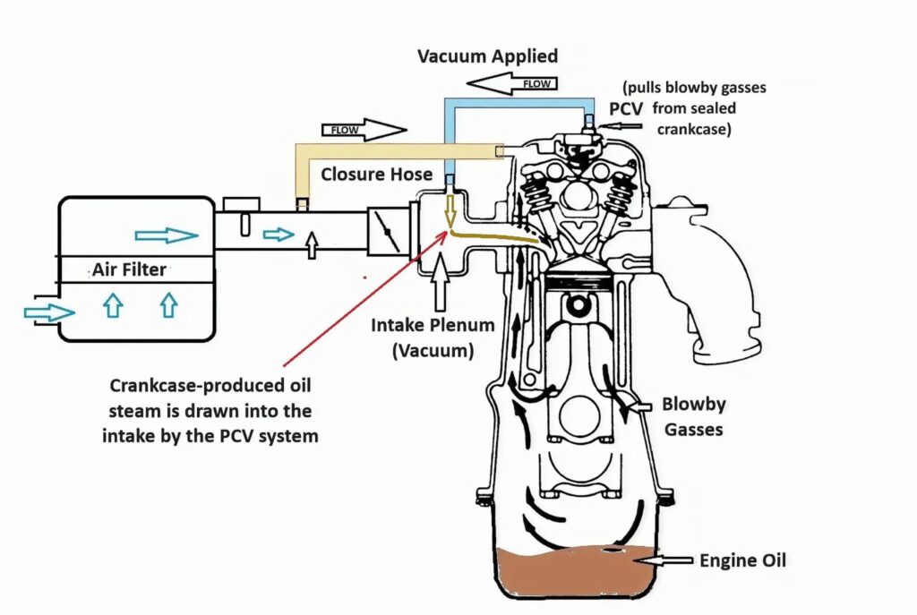
Positive crankcase ventilation is the controlled path that evacuates blow-by gases and oil vapor from the crankcase and routes them back into the intake to be burned. When it works correctly, the system maintains a slight vacuum in the crankcase, which reduces sludge formation, oil leaks, and mixture problems at idle.
Why the PCV system exists
The PCV system is an emissions and pressure-control circuit that keeps the crankcase from becoming a pressurized, fuel-laced vapor tank. Its job is to purge moisture and combustion byproducts from the crankcase while preventing those hydrocarbons from venting into the open air. Without this control, crankcase blow-by can account for a significant share of hydrocarbon emissions.

Pro Tips are nuggets of information direct from ASE-certified automobile technicians working with CarParts.com, which may include unique, personal insights based on their years of experience working in the automotive industry. These can help you make more informed decisions about your car.
Pro Tip: Also, gasoline combustion produces a gallon of water for every gallon of gas burned, and so, particularly when the engine is cold, some of the blow-by will be steam, which can cause dreadful sludge problems if the engine is operated frequently without being allowed to warm up. The PCV system won’t prevent sludge on an engine that is always operated without warming up.
In the term “PCV valve,” PCV stands for positive crankcase ventilation. The valve itself is the calibrated metering device that makes the circuit behave like a controlled air leak rather than a massive vacuum leak. Modern closed designs route vapors back through the engine for reburning.
Warning: Unplugging, rerouting, or venting this system to atmosphere is considered emissions tampering under U.S. federal law and often creates new oil-control problems.
How crankcase ventilation flow changes with driving conditions
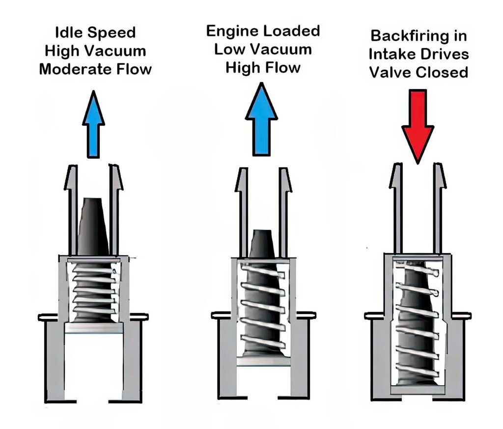
The system works because a pressure difference moves vapors while the metering device adjusts flow to keep the engine stable. During normal operation, the circuit restricts flow when intake vacuum is high, then allows more flow as vacuum drops at part throttle.
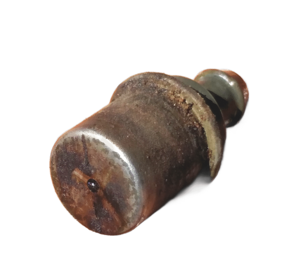
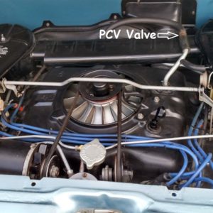
Note: Some PCV systems only have a fixed orifice metering port in the valve cover or in a pseudo-PCV valve that’s just a hollow shell with no internal parts (see photo). Jeep 4.0L engines (inline 6) have a fixed orifice arrangement like this, but it’s a plastic part in the rear top of the valve cover.
What changes with conditions:
- Idle and decel: High manifold vacuum pulls the metering device toward a low-flow position to protect idle quality.
- Light-load cruise: Moderate vacuum and steady blow-by usually produce the most effective crankcase scavenging.
- Heavy load: Low vacuum means the system relies more on alternate routing and blow-by pressure to keep vapors moving.
- Reverse-pressure protection: Many designs close quickly against backflow to reduce the risk of flame travel.
Tip: Turbo engines often split crankcase ventilation into a vacuum path and a boost path. A fault in the boost path can show up as oil ingestion only under load, even if idle behavior seems normal.
Common PCV layouts and components
On a typical PCV system, fresh filtered air enters the crankcase area, vapors pass through internal baffles or a separator, and the metering device connects to an intake vacuum source or the turbo inlet tract. Some engines use a fixed orifice or diaphragm-style regulator integrated into a cover, so there may be no small serviceable part to swap out.
Common components and failure points:
- The fresh-air inlet from the air filter housing, which can plug with sludge or ice
- Oil separation baffles or an external separator, which can clog and drive oil consumption
- The metering device or integrated regulator, which can stick or develop a torn diaphragm
- Molded PCV hoses and other vapor lines that can crack, collapse, or soften from oil exposure
Note: Because this circuit is calibrated, a look-alike replacement that flows differently can cause a lean idle, changes in oil consumption, or repeat fault codes. Even using the wrong part number PCV valve can cause this issue on MAF-equipped engines.
Symptoms that point to a crankcase ventilation problem
Most complaints come from too little crankcase flow, which raises pressure, or too much unmetered flow, which mimics a vacuum leak. Use the pattern of symptoms rather than a single one to decide what to test next.
| Symptom you see | Likely direction | What to check first |
| Oil seepage at gaskets and seals, dipstick popping up | Excess pressure | Blocked fresh-air inlet, restricted separator passages, collapsed vapor line |
| Whistling or honking at idle, oil cap hard to remove | Excess vacuum | Torn diaphragm or restricted fresh-air inlet |
| Rough idle or lean codes that improve off-idle | Vacuum leak effect | Suction at vents, scan fuel trims at idle, inspect regulator area |
| Sludge or milky residue under oil cap on short trips | Low purge flow | Verify flow, then shorten service interval |
| Oil film in intake tract or intercooler piping | Poor separation or overload | Separator condition, routing integrity, engine blow-by level |
Warning: Excess vacuum can damage seals just as excess pressure can, especially on engines designed to hold only a slight under-pressure.
Fast diagnostic checks that prevent parts swapping
A few quick checks can tell you whether the problem is airflow, calibration, or engine wear.
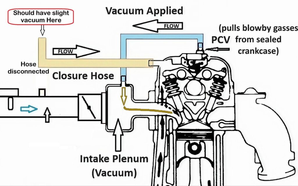
First, you can remove the closure hose with the engine running and put your finger over it. You should feel a slight vacuum if the PCV has sufficient flow (see drawing).
Tools that help:
- A scan tool that shows short-term and long-term fuel trims
- A low-range vacuum or pressure gauge, or a simple water manometer
- A smoke machine, if you have access to one
1. Do a hot-idle sanity check
- Warm the engine fully.
- Listen for whistling or honking near the cam cover area.
- Loosen the oil fill cap slightly and note whether the noise and idle change sharply.
2. Verify the fresh-air inlet is open
- Inspect the fresh-air path from the air filter housing to the engine.
- Look for oil sludge, soft spots, or icing that could restrict makeup air.
3. Pinch-test the manifold-side vapor feed at idle
- Briefly pinch the vapor line that feeds the intake vacuum source, then release it.
- No change suggests a restriction or no flow. A large change suggests excessive flow or wrong calibration.
4. Use fuel trims as a decision point
- At warm idle, note the fuel trims.
- If trims are strongly positive at idle but improve with light throttle, suspect unmetered air entering through the crankcase ventilation circuit.
5. Measure crankcase vacuum rather than guessing
- Connect your gauge to the dipstick tube with a sealing adapter.
- Expect a small vacuum. Many pressure-controlled systems target under-pressure in the tens of millibar range at idle, and the actual reading depends on how well the engine seals. BMW service information publishes specific under-pressure ranges for many engines, which illustrates how precisely this circuit is engineered.
- Pressure at idle points to a restriction or excessive blow-by. Strong vacuum points to diaphragm failure, wrong parts, or a blocked fresh-air inlet.
6. Smoke-test when symptoms conflict
- Feed smoke into the crankcase through a sealed oil-fill adapter.
- Repair external leaks first, because large leaks prevent the crankcase from reaching its intended vacuum.
Example scenario: A Chevy Cruze 1.4T with a P0171 lean code and a loud idle whistle often traces back to a torn crankcase pressure-control diaphragm integrated into the cam cover assembly. Confirm the whistle changes when the dipstick is lifted, then verify strong suction at the vent and check fuel trim behavior before replacing unrelated intake parts.
Repairs, maintenance, and when to suspect deeper engine issues
The correct repair restores original flow characteristics and sealing.
Best practices:
- Use the exact application-specific part number for the metering device or integrated regulator.
- Many older engines treated this as routine service, and 30,000 to 50,000 miles was a common interval when the part was easy to access.
- Replace hardened seals and brittle molded lines at the same time to avoid creating a new unmetered-air leak.
- If sludge is present, service the separator components and shorten oil change intervals until the engine stays clean.
- After repairs, recheck fuel trims and crankcase vacuum at warm idle.
Mistakes to avoid:
- Forcing high shop air pressure into the crankcase to find leaks. Use smoke or very low pressure only.
- Assuming every oil leak is caused by excess pressure. Excess vacuum can also pull oil past seals.
When PCV is not the main problem:
- If crankcase pressure remains high even with confirmed open passages, the engine may have excessive blow-by from ring or cylinder wear.
- If oil ingestion is heavy only under sustained boost, investigate turbocharger condition and the boost-side routing.
One final note for code-driven diagnosis: on some Mercedes C300 applications, crankcase ventilation performance faults are tied to specific service actions such as software updates or intake-line assembly fixes. Follow the fault code test plan before replacing major parts.
Keep Reading: Related Posts



Any information provided on this Website is for informational purposes only and is not intended to replace consultation with a professional mechanic. The accuracy and timeliness of the information may change from the time of publication.